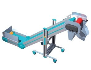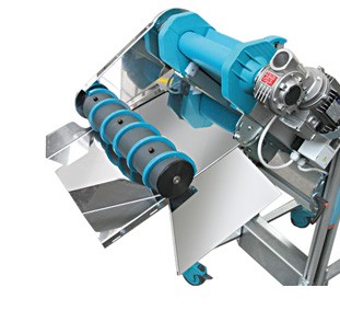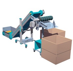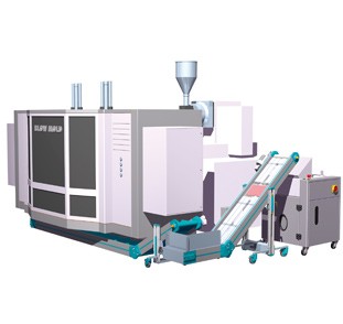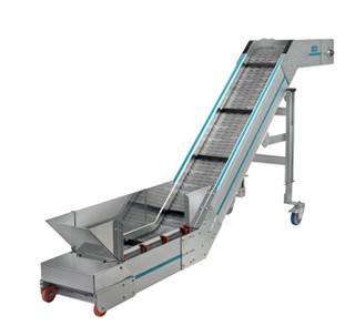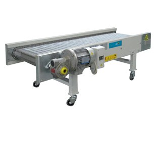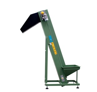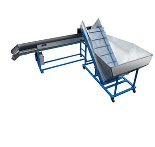
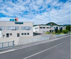
Company image
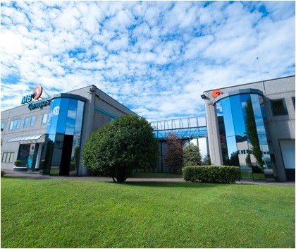
MB Conveyors

Produkcja rozwiązań, maszyn i systemów na zamówienie dla każdego zastosowania i potrzeb w dziedzinie obsługi przemysłowej: w ten sposób MB Conveyors realizują swoją misję.

Firma MB Conveyors może pochwalić się 25-letnim doświadczeniem w dziedzinie mechaniki, co wyjaśnia jej pasję do produktu i dbałość o szczegóły.

Funkcjonalność i rentowność systemu, obsługa i wsparcie klienta, badania i rozwój wspierane przez ekspertów i procesy; są to główne elementy łańcucha wartości, który rozpoczyna się i kończy bezproblemową integracją firmy z naszymi klientami.

Jakość zapewniona jest dzięki przeprowadzaniu rygorystycznych testów na każdym etapie produkcji, przy użyciu najnowszej generacji systemów produkcyjnych i wyborze wyłącznie materiałów najwyższej jakości.

Zespół MB Conveyors zawsze umieszczał idee klientów w centrum swojej pracy, wyrażając w ten sposób swój profesjonalizm.
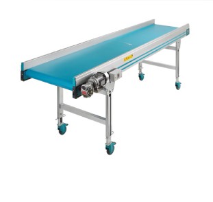
 

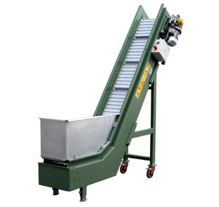
  • Taśmociągi
    Rozwiń
    Zwiń

      Produkcja indywidualnych rozwiązań, urządzeń i systemów do każdego zastosowania i potrzeb w dziedzinie przenoszenia przemysłowego: w ten sposób firma MB Conveyors realizuje swoją misję.

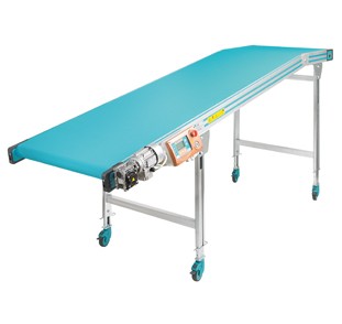
    • Standardowe przenośniki taśmowe
      Rozwiń
      Zwiń
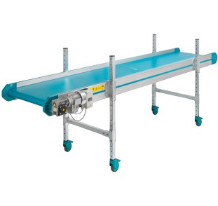
      • PA – standardowy płaski przenośnik taśmowy
        Rozwiń
        Zwiń


          • stabilna rama wykonana z wytłaczanego profilu aluminiowego, Alloy 6060, zabezpieczona anodyzacją o średniej grubości powłoki 15 mikronów
          • standardowa, odporna na przecięcie i olej taśma, z gładką zieloną powłoką poliuretanową (ref. Pantone 320); wulkanizowane połączenie taśmy
          • minimalna i maksymalna odporność termiczna taśmy: -10°C do + 90°C
          • standardowy zespół napędowy, składający się z 0,12 kW, trójfazowego, asynchronicznego silnika, sprzężonego z reduktorem ślimakowym ze stałym smarowaniem
          • stała standardowa prędkość przenośnika 3 m/min
          • przenośnik w komplecie z wyłącznikiem Siemens Start / Stop / wyłącznikiem silnika, z kablem 5 m i wtyczką 4P CE (3 fazy + masa)
          • standardowe napięcie zasilania silnika 400 V / 50 Hz


      • PAR – przenośnik z regulowaną płaską częścią górną
        Rozwiń
        Zwiń


          • stabilna rama wykonana z wytłaczanego profilu aluminiowego, Alloy 6060, zabezpieczona anodyzacją o średniej grubości powłoki 15 mikronów
          • standardowa, odporna na przecięcie i olej taśma, z zieloną powłoką PVC o wysokiej przyczepności (ref. Pantone 320); wulkanizowane połączenie taśmy
          • minimalna i maksymalna odporność termiczna taśmy: -10°C do + 60°C
          • standardowy zespół napędowy, składający się z 0,12 kW, trójfazowego, asynchronicznego silnika, sprzężonego z reduktorem ślimakowym ze stałym smarowaniem
          • stała standardowa prędkość przenośnika 3 m/min
          • przenośnik w komplecie z wyłącznikiem Siemens Start / Stop / wyłącznikiem silnika, z kablem 5 m i wtyczką 4P CE (3 fazy + uziemienie)
          • standardowe napięcie zasilania silnika 400 V / 50 Hz


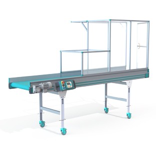
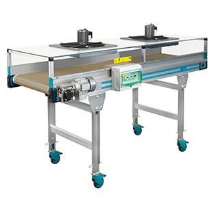
      • PA Robot – przenośnik do pracy z robotem
        Rozwiń
        Zwiń


          • Zdjęcie obok pokazuje przenośnik PA wraz z osłonami z poliwęglanu.
            Stwierdzono, że najbardziej odpowiedni do tego celu jest model PA przenośnika (przekrój poprzeczny 110×30 mm) ze względu na:
            – mocną, solidną konstrukcję;
            – możliwość zainstalowania / usunięcia bocznych paneli zabezpieczających;
            – możliwość zainstalowania fotokomórek sterujących nad panelami bocznymi i wewnątrz nich;
            – łatwość instalacji konstrukcji ochronnej robota.


      • PA 180 – płaski przenośnik taśmowy do ciężkich ładunków
        Rozwiń
        Zwiń


          • stabilna rama wykonana z wytłaczanego profilu aluminiowego, Alloy 6060, zabezpieczona anodyzacją o średniej grubości powłoki 15 mikronów
          • standardowa, odporna na przecięcie i olej taśma, z czarną powłoką poliuretanową; wulkanizowane połączenie taśmy
          • minimalna i maksymalna odporność termiczna taśmy: -10°C do + 90°C
          • standardowy zespół napędowy, składający się z trójfazowego silnika asynchronicznego o mocy odpowiedniej do wymiarów i wymaganych mocy, sprzężonego z reduktorem ślimakowym ze stałym smarowaniem
          • stała standardowa prędkość przenośnika 5 m/min
          • przenośnik w komplecie z wyłącznikiem Siemens Start / Stop / wyłącznikiem silnika, z kablem 5 m i wtyczką 4P CE (3 fazy + masa)
          • standardowe napięcie zasilania silnika 400 V / 50 Hz


      • Łuki
        Rozwiń
        Zwiń


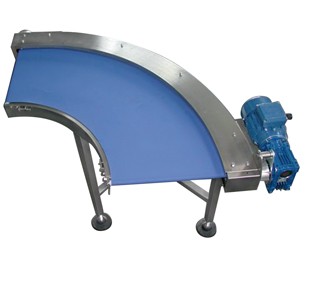
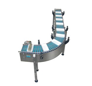
          • zdjęcie powyżej pokazuje wersję F.D.A. przenośnika z łukiem 90° z rolkami równoległymi
          • w tym rozwiązaniu wszystkie części konstrukcyjne przenośnika wykonane są ze stali nierdzewnej 304 AISI
          • przenośnik odpowiedni do transportu żywności i produktów farmaceutycznych
          • przenośnik taśmowy, w tym przypadku zgodnie z życzeniem klienta w kolorze niebieskim, jest całkowicie zgodny ze standardami F.D.A.


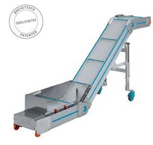
      • N-TR – przenośnik o regulowanym nachyleniu
        Rozwiń
        Zwiń

          • stabilna rama wykonana z wytłaczanego profilu aluminiowego, Alloy 6060, zabezpieczona anodyzacją o średniej grubości powłoki 15 mikronów
          • standardowa, odporna na przecięcie i olej taśma, z gładką zieloną powłoką poliuretanową (ref. Pantone 320); z listwami zgrzewanymi o wysokości h=30 mm co 400 mm; wulkanizowane połączenie taśmy
          • minimalna i maksymalna odporność termiczna taśmy: -10°C do + 90°C
          • standardowy zespół napędowy, składający się z 0,12 kW, trójfazowego, asynchronicznego silnika, sprzężonego z reduktorem ślimakowym ze stałym smarowaniem
          • stała standardowa prędkość przenośnika 3 m/min
          • przenośnik w komplecie z wyłącznikiem Siemens Start / Stop / wyłącznikiem silnika, z kablem 5 m i wtyczką 4P CE (3 fazy + uziemienie)
          • standardowe napięcie zasilania silnika 400 V / 50 Hz


      • N-CPR – przenośnik o zmiennym kierunku
        Rozwiń
        Zwiń


          • stabilna rama wykonana z wytłaczanego profilu aluminiowego, Alloy 6060, zabezpieczona anodyzacją o średniej grubości powłoki 15 mikronów
          • standardowa, odporna na przecięcie i olej taśma, z gładką zieloną powłoką poliuretanową (ref. Pantone 320); z listwami zgrzewanymi o wysokości h=30 mm co 400 mm; wulkanizowane połączenie taśmy
          • minimalna i maksymalna odporność termiczna taśmy: -10°C do + 90°C
          • standardowy zespół napędowy, składający się z 0,12 kW, trójfazowego, asynchronicznego silnika, sprzężonego z reduktorem ślimakowym ze stałym smarowaniem
          • stała standardowa prędkość przenośnika 3 m/min
          • przenośnik w komplecie z wyłącznikiem Siemens Start / Stop / wyłącznikiem silnika, z kablem 5 m i wtyczką 4P CE (3 fazy + uziemienie)
          • standardowe napięcie zasilania silnika 400 V / 50 Hz
          • na życzenie dostępna jest wersja Easy Line (zdjęcie poniżej) z uproszczoną konstrukcją nóg podtrzymujących, co pozwala na zmniejszenie o około 15% ostatecznej ceny przenośników


          Wersja Easy Line

      • N-CPTR – przenośnik o zmiennym kierunku
        Rozwiń
        Zwiń


          • stabilna rama wykonana z wytłaczanego profilu aluminiowego, Alloy 6060, zabezpieczona anodyzacją o średniej grubości powłoki 15 mikronów
          • standardowa, odporna na przecięcie i olej taśma, z gładką zieloną powłoką poliuretanową (ref. Pantone 320); z listwami zgrzewanymi o wysokości h=30 mm co 400 mm; wulkanizowane połączenie taśmy
          • minimalna i maksymalna odporność termiczna taśmy: -10°C do + 90°C
          • standardowy zespół napędowy, składający się z 0,12 kW, trójfazowego, asynchronicznego silnika, sprzężonego z reduktorem ślimakowym ze stałym smarowaniem
          • stała standardowa prędkość przenośnika 3 m/min
          • przenośnik w komplecie z wyłącznikiem Siemens Start / Stop / wyłącznikiem silnika, z kablem 5 m i wtyczką 4P CE (3 fazy + uziemienie)
          • standardowe napięcie zasilania silnika 400 V / 50 Hz
          • na życzenie dostępna jest wersja Easy Line z uproszczoną konstrukcją nóg podtrzymujących, co pozwala na zmniejszenie o około 15% ostatecznej ceny przenośników


      • N-PA – przenośnik płaski Easy Line
        Rozwiń
        Zwiń


          • stabilna rama wykonana z wytłaczanego profilu aluminiowego, Alloy 6060, zabezpieczona anodyzacją o średniej grubości powłoki 15 mikronów
          • standardowa, odporna na przecięcie i olej taśma, z gładką zieloną powłoką poliuretanową (ref. Pantone 320); wulkanizowane połączenie taśmy
          • minimalna i maksymalna odporność termiczna taśmy: -10°C do + 90°C
          • standardowy zespół napędowy, składający się z 0,12 kW, trójfazowego, asynchronicznego silnika, sprzężonego z reduktorem ślimakowym ze stałym smarowaniem
          • stała standardowa prędkość przenośnika 3 m/min
          • przenośnik w komplecie z wyłącznikiem Siemens Start / Stop / wyłącznikiem silnika, z kablem 5 m i wtyczką 4P CE (3 fazy + uziemienie)
          • standardowe napięcie zasilania silnika 400 V / 50 Hz


    • Pionowe przenośniki taśmowe
      Rozwiń
      Zwiń
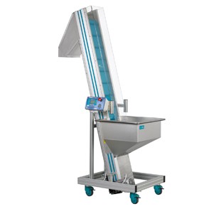
      • Pionowy przenośnik taśmowy EV 600
        Rozwiń
        Zwiń


          • stabilna rama wykonana z wytłaczanego profilu aluminiowego, Alloy 6060, zabezpieczona anodyzacją o średniej grubości powłoki 15 mikronów
          • standardowa, odporna na przecięcie i olej taśma, z gładką zieloną powłoką poliuretanową (ref. Pantone 320); z listwami zgrzewanymi o wysokości h=30 mm co 150 mm; wulkanizowane połączenie taśmy
          • minimalna i maksymalna odporność termiczna taśmy: -10°C do + 90°C
          • standardowy zespół napędowy, składający się z 0,18 kW, trójfazowego, asynchronicznego silnika, sprzężonego z reduktorem ślimakowym ze stałym smarowaniem
          • stała standardowa prędkość przenośnika 12 m/min
          • przenośnik w komplecie z wyłącznikiem Siemens Start / Stop / wyłącznikiem silnika, z kablem 5 m i wtyczką 4P CE (3 fazy + uziemienie)
          • standardowe napięcie zasilania silnika 400 V / 50 Hz


      • Pionowy przenośnik taśmowy EV 800 – EV 1000
        Rozwiń
        Zwiń


          • stabilna rama wykonana z wytłaczanego profilu aluminiowego, Alloy 6060, zabezpieczona anodyzacją o średniej grubości powłoki 15 mikronów
          • standardowa, odporna na przecięcie i olej taśma, z gładką zieloną powłoką poliuretanową (ref. Pantone 320); z listwami zgrzewanymi o wysokości h=30/50 mm co 150 mm; wulkanizowane połączenie taśmy
          • minimalna i maksymalna odporność termiczna taśmy: -10°C do + 90°C
          • standardowy zespół napędowy, składający się z 0,18 kW, trójfazowego, asynchronicznego silnika, sprzężonego z reduktorem ślimakowym ze stałym smarowaniem
          • stała standardowa prędkość przenośnika 12 m/min
          • przenośnik w komplecie z wyłącznikiem Siemens Start / Stop / wyłącznikiem silnika, z kablem 5 m i wtyczką 4P CE (3 fazy + uziemienie)
          • standardowe napięcie zasilania silnika 400 V / 50 Hz


    • Taśmociągi z chłodzeniem
      Rozwiń
      Zwiń

        Czasami mamy do czynienia z produkcją, która wymaga chłodzenia produktów podczas ich transportu na przenośnikach taśmowych.

        W takich przypadkach oferujemy nasze niezawodne przenośniki MB Conveyors z różnymi systemami chłodzenia.

      • Chłodzący system przenoszenia z wentylatorami helikalnymi
        Rozwiń
        Zwiń


          • połączenie siatkowego przenośnika taśmowego i przepływu powietrza wytwarzanego przez zainstalowane wentylatory elektryczne zapewnia idealne warunki do chłodzenia produktu podczas transportu
          • tunel, w którym zainstalowane są wentylatory elektryczne, wykonany jest z poliwęglanu z aluminiową ramą nośną
          • regulacja prędkości przenośnika jest trzecim ważnym elementem, który uzupełnia i poprawia tę kombinację. Do tej funkcji zwykle używany jest panel sterowania MB


      • System chłodzący z wentylatorami promieniowymi
        Rozwiń
        Zwiń


          • zdjęcie poniżej pokazuje przenośnik CPT wykonany z profilu aluminiowego PA 180 i z plastikowym pasem
          • specjalny kształt wewnętrznej struktury tworzy przepływ powietrza o stałym natężeniu przepływu i ciśnieniową głowicę, która uderza w produkt podczas jego ruchu wzdłuż przenośnika
          • zwróć uwagę na tunel z poliwęglanu zainstalowany w celu ochrony transportowanego produktu


      • System przenoszenia z chłodzeniem wodnym
        Rozwiń
        Zwiń


          • zdjęcie powyżej pokazuje system, w którym elementem chłodzącym jest woda
          • produkt transportowany jest zanurzony w wodzie na całej długości zbiornika z górnego przenośnika PA
          • pod koniec drogi produkt jest odbierany przez górną część przenośnika CP i wyjmowany ze zbiornika
          • prędkości przenośnika płaskiego i CP są regulowane (zobacz panele sterowania MB)


    • Separatory
      Rozwiń
      Zwiń
      • Przenośnik N-CPST z separatorem łopatkowym
        Rozwiń
        Zwiń


          • stabilna rama wykonana z wytłaczanego profilu aluminiowego, Alloy 6060, zabezpieczona anodyzacją o średniej grubości powłoki 15 mikronów
          • standardowa, odporna na przecięcie i olej taśma, z zieloną powłoką PVC o wysokiej przyczepności (ref. Pantone 320); wulkanizowane połączenie taśmy
          • minimalna i maksymalna odporność termiczna taśmy: -10°C do + 60°C
          • standardowy zespół napędowy, składający się z 0,12 kW, trójfazowego, asynchronicznego silnika, sprzężonego z reduktorem ślimakowym ze stałym smarowaniem
          • stała standardowa prędkość przenośnika 3 m/min
          • przenośnik w komplecie z wyłącznikiem Siemens Start / Stop / wyłącznikiem silnika, z kablem 5 m i wtyczką 4P CE (3 fazy + uziemienie)
          • standardowe napięcie zasilania silnika 400 V / 50 Hz
          • na życzenie dostępna jest wersja Easy Line z uproszczoną konstrukcją nóg podtrzymujących (zdjęcie poniżej), co pozwala na zmniejszenie o około 15% ostatecznej ceny przenośników


          Wersja Easy Line


      • Separator bębnowy SR
        Rozwiń
        Zwiń


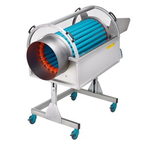
          • separator z bębnem obrotowym składający się z 24 rolek PVC o średnicy 50 mm i długości 800 mm (odległość między rolkami można regulować RĘCZNIE)
          • każdy separator ma własny falownik do regulacji prędkości obrotowej bębna; możliwy zakres regulacji: minimum 4 obroty/minutę, maksymalnie 20 obrotów/minutę
          • w separatorze SR dostępna jest ręczna regulacja odległości między rolkami
          • rama bębna jest podtrzymywana przez dwa gwintowane pręty, które umożliwiają regulację nachylenia bębna po obu stronach
          • znalezienie właściwego stosunku prędkości obrotowej bębna do lekkiego przeciwnego nachylenia pozwala na skuteczne oddzielenie produktu od wlewka
          • w standardowych separatorach bęben rolkowy można wymienić na bęben perforowany
          • napięcie zasilania silnika: 220 V / 50 Hz, jednofazowe


      • Separator bębnowy SM
        Rozwiń
        Zwiń


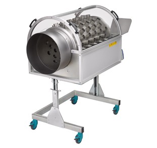
          • separator z perforowanym bębnem obrotowym wykonanym z arkusza AISI 304, zwykle z małymi rurkami antypoślizgowymi
          • każdy separator ma własny falownik do regulacji prędkości obrotowej bębna; możliwy zakres regulacji: minimum 4 obroty/minutę, maksymalnie 20 obrotów/minutę
          • w separatorze SM średnica otworów i konieczność spawania rur antypoślizgowych zależy od kształtu produktu i wlewka
          • rama bębna jest podtrzymywana przez dwa gwintowane pręty, które umożliwiają regulację nachylenia bębna po obu stronach
          • znalezienie właściwego stosunku prędkości obrotowej bębna do lekkiego przeciwnego nachylenia pozwala na skuteczne oddzielenie produktu od wlewka
          • napięcie zasilania silnika: 220 V / 50 Hz, jednofazowe


      • Separator spiralny FSRV z podstawą
        Rozwiń
        Zwiń


          • separator z niezależną podstawą na ziemi (do pozycjonowania przed przenośnikiem tylko w razie potrzeby)
          • zsyp separatora wykonany z polerowanego AISI 304
          • zespół przekładni umieszczony po prawej stronie, moc 0,09 kW, z ogranicznikiem momentu obrotowego
          • prędkość obrotowa wałka rozdzielającego: 70 obr./min
          • uruchamianie i zatrzymywanie separatora za pomocą wyłącznika silnika Siemens
          • standardowe napięcie zasilania silnika 400 V/50 Hz


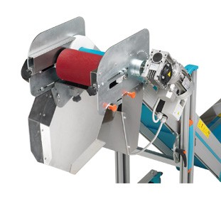
      • Pojedynczy separator rolkowy N-SRS zainstalowany na przenośniku
        Rozwiń
        Zwiń


          • dostępne są trzy modele:
            1 – model N-SRS 1 dla przenośnika o szerokości roboczej 240 mm
            2 – model N-SRS 2 dla przenośnika o szerokości roboczej 340 mm
            3 – model N-SRS 3 dla przenośnika o szerokości roboczej 440 mm
          • separator ten przeznaczony jest do instalacji na przenośnikach N-CPR i N-CPTR
          • przenoszenie ruchu z przenośnika do pojedynczego wałka separatora odbywa się za pomocą pasa Pu
          • dzięki elastyczności pasa odległość między rolką separatora a przenośnikiem może być regulowana od minimum 5 mm do maksymalnie 20 mm
          • przenośnik, na którym zainstalowany jest separator N-SRS, musi mieć taśmę z listwami o maksymalnej wysokości 20 mm


          Separator N-SRS z przenośnikiem N-CPR


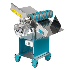
      • Separator spiralny N-FSRV zainstalowany na przenośniku
        Rozwiń
        Zwiń


          • dostępne są trzy modele separatorów N-FSRV:
            1 – model N-FSRV 1 dla przenośnika o szerokości roboczej 240 mm
            2 – model N-FSRV 2 dla przenośnika o szerokości roboczej 340 mm
            3 – model N-FSRV 3 dla przenośnika o szerokości roboczej 440 mm
          • separator wlewków N-FSRV instalowany jest bezpośrednio na przenośniku, z którego spirala uzyskuje ruch obrotowy
          • przeniesienie ruchu z przenośnika na rolkę spiralną odbywa się za pomocą pasa Pu. Ze względów bezpieczeństwa pasek jest wystarczająco naciągnięty do obrotu. W przypadku najmniejszej przeszkody rolka spiralna zatrzymuje się


          N-FSRV z przenośnikiem N-CPR


    • Detektory metali
      Rozwiń
      Zwiń

        Detektory metalu dbają o czystość materiału i uwalniają go od zanieczyszczeń o charakterze metalicznym.
      • Płytowy detektor metalu MD
        Rozwiń
        Zwiń


          Powyższy rysunek przedstawia płytowy wykrywacz metalu, umieszczony wewnątrz przenośnika N-CPR, w celu wykrycia zanieczyszczeń metalicznych, gdy materiał przenoszony jest z urządzenia formującego do młyna.
          Płytowy detektor metalu nadaje się idealnie także do zastosowań poza formowaniem wtryskowym, gdy do czynienia mamy z prawie ciągłym przepływem materiału, który zwykle jest dobrze rozłożony na przenośniku.


          CP kompletny z wykrywaczem metalu


      • Tunelowy detektor metalu MD
        Rozwiń
        Zwiń


          Poniższy rysunek przedstawia tunelowy wykrywacz metalu zainstalowany na przenośniku MB, w celu wykrywania zanieczyszczeń metalicznych zawartych w dużych masach materiału i/lub w produktach o dużych rozmiarach. Rozwiązania te są zwykle proponowane w dziedzinie odzysku tworzyw sztucznych.


          MB 180 w komplecie z tunelowym wykrywaczem metalu


      • Rolka magnetyczna MD
        Rozwiń
        Zwiń


          Rolka magnetyczna proponowana jest tylko wtedy, gdy wykryte zanieczyszczenia metaliczne są żelazne, a zatem wrażliwe na pole magnetyczne.

          Rolka składa się z szeregu magnesów sektorowych, przymocowanych do siebie i zainstalowana jest jako rolka napędowa.

          Zanieczyszczenia żelazne, wychwycone przez pole magnetyczne, nie wpadają do wlotu młyna, ale są przenoszone na zewnątrz i rozładowywane do rynny przeznaczonej do tego celu.


    • Składowanie
      Rozwiń
      Zwiń
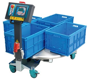
      • Stoły obrotowe TVC
        Rozwiń
        Zwiń


          • stoły obrotowe zaczynają się od podstawowego modelu zwanego TV, a następnie, w zależności od ich zastosowania, dzielą się na:
            – stoły obrotowe do pojemników, będące modelem TVC
            – stoły obrotowe do worków, będące modelem TVS
          • cechy techniczne podstawowego modelu stołu obrotowego o nazwie TV:
            płyta wykonana z AISI 430 0 grubości 3 mm, na której spoczywają stoły
          • funkcje TVC (stół obrotowy do pojemników) i TVS (stół obrotowy do worków) zdefiniowane są w ofercie handlowej. Model i cechy w zależności od typu i wymiarów pojemnika
          • napięcie zasilania silnika standardowych stołów obrotowych to 400 V / 50 Hz


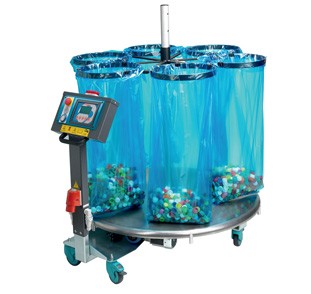
      • Stoły obrotowe TVS
        Rozwiń
        Zwiń


          • stoły obrotowe zaczynają się od podstawowego modelu zwanego TV, a następnie, w zależności od ich zastosowania, dzielą się na:
            – stoły obrotowe do pojemników, będące modelem TVC
            – stoły obrotowe do worków, będące modelem TVS
          • cechy techniczne podstawowego modelu stołu obrotowego o nazwie TV:
            płyta wykonana z AISI 430 o grubości 3 mm, na której spoczywają stoły
          • funkcje TVC (stół obrotowy do pojemników) i TVS (stół obrotowy do worków) zdefiniowane są w ofercie handlowej. Model i cechy w zależności od typu i wymiarów pojemnika
          • napięcie zasilania silnika standardowych stołów obrotowych to 400 V / 50 Hz


      • Rozdzielacz DUCK (Kaczka)
        Rozwiń
        Zwiń

          • rozdzielacz DUCK (Kaczka) może pracować stosując dwie różne metody, które nie są ze sobą kompatybilne:
            – używając sygnału beznapięciowego A/C, pochodzącego z wtryskarki w każdym cyklu formowania
            – ustawiając czas napełniania dla każdego pojemnika
          • zsyp rozdzielacza DUCK może obracać się o 360° i może prowadzić produkt do dowolnego punktu na swojej drodze
          • wydajność: nie przekracza 2 kg dla każdego produktu
          • zainstalowana moc silnika dla obrotów zsypu: 0,06 kW
          • standardowe napięcie zasilania silnika: 400 V / 50 Hz


      • System składowania CAR
        Rozwiń
        Zwiń


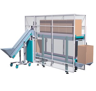
          • zdjęcie powyżej pokazuje system do przechowywania produktów w pojemnikach na konstrukcji z dwoma płaskimi przenośnikami i poprzecznym trawersem
          • uzupełnieniem systemu jest osłona przeciwpyłowa z kształtowanego profilu aluminiowego z płytami poliwęglanowymi
          • zwróć uwagę na przenośnik ładujący, który działając synchronicznie z systemem, przenosi i rozładowuje produkt do pojemników


      • System składowania CAV
        Rozwiń
        Zwiń


          • rysunek powyżej pokazuje pionową karuzelę z dwoma piętrami z pionowym przenośnikiem bocznym
          • górny przenośnik wypełniony jest pustymi pojemnikami. Gdy pojemnik zostaje napełniony, winda przenosi go na przenośnik dolny
          • obszar pionowego ruchu windy wyposażony jest w specjalne urządzenie ochronne


      • System składowania Napełnianie
        Rozwiń
        Zwiń


          • zdjęcie powyżej pokazuje przenośnik CPT do zbierania i przenoszenia produktu do przenośnika-dystrybutora PA w celu przechowywania w dwóch pojemnikach
          • logika działania obejmuje zliczanie formowanych elementów, które mają być przechowywane w pojemniku
          • techniczne i wymiarowe cechy systemu określane są od czasu do czasu, w zależności od potrzeb
          • rysunek poniżej pokazuje aplikację widoczną powyżej
          • cechą charakterystyczną tego systemu jest stały ruch przenośnika-dystrybutora PA wzdłuż jego osi wzdłużnej
          • ta szczególna funkcja umożliwia równomierne napełnianie pojemnika, unikając centralnej akumulacji


      • System składowania Ważenie
        Rozwiń
        Zwiń


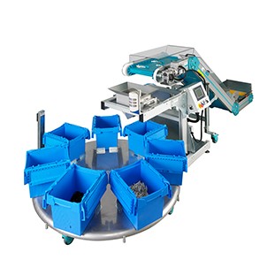
          • zdjęcie przedstawia grupę składającą się z przenośnika do odbierania i przenoszenia produktów, leja do ważenia ich w celu przechowywania w pojemnikach z wysoką dokładnością zliczania oraz stołu obrotowego do sekwencyjnego napełniania 7 pojemników
          • system ten pozwala na bardzo precyzyjne przechowywanie produktów w pojemnikach i znaczną autonomię napełniania poza wtryskarką


      • Mieszalnik pionowy MI
        Rozwiń
        Zwiń


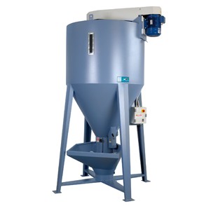
          • mieszalnik pionowy MI to rozwiązanie, które zawsze było używane do mieszania granulatów tworzyw sztucznych
          • mieszalnik pionowy składa się z ramy zewnętrznej, wykonanej z malowanej blachy, i wewnętrznego ślimaka wewnątrz rury do mieszania zawartości
          • materiał, który ma być mieszany, jest podawany do leja załadowczego, ślimak odbiera go od dołu i przenosi go do góry, uwalniając go na górze, rozprowadzając go wewnątrz korpusu mieszalnika z promieniem 360°. Po około 15/20 minutach materiał jest idealnie wymieszany
          • zasilacz mieszalnika zawiera panel sterowania zbudowany zgodnie ze standardami EEC, z funkcjami Start i Stop oraz ustawieniami czasu biegu i zatrzymania
          • klapy rewizyjne przenośnika ślimakowego i mieszalnika są zabezpieczone mikrowyłącznikami bezpieczeństwa


      • Mieszalnik MI1
        Rozwiń
        Zwiń


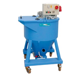
          • zdjęcie powyżej pokazuje pionowy mieszalnik do mieszania małych ilości produktu lub, jak to często bywa, do testów formowania lub badania materiałów
          • jest zatem odpowiedni, gdy partie produktu nie są bardzo duże
          • zasada mieszania pozostaje niezmieniona: na życzenie ślimak jest zamknięty w rurze, materiał jest podawany od góry. Wymieszany produkt jest zwykle pobierany za pomocą króćca ssącego i podawany do jednej z dwóch stożkowych rur bocznych pojemnika
          • zasuwa do szybkiego opróżnienia i/lub czyszczenia wewnątrz zbiornika mieszalnika i pokrywy zbiornika chroniona jest przez mikrowyłączniki


    • Przenośniki z taśmą plastikową i metalową
      Rozwiń
      Zwiń
      • Taśma plastikowa
        Rozwiń
        Zwiń


          • boczna krawędź pojemnika nie otwiera się nawet podczas obracania się listwy łopatki na kołach napędowych
          • powierzchnia styku taśmy z tworzywa sztucznego ma nieco podwyższoną przyczepność
          • wzmocniona taśma plastikowa PP, kolor RAL 9002
          • temperatura pracy + 1°C do około 130°C
          • standardowa listwa: h = 35 mm modułowa, skok min. 25 mm.
          • możliwość zastosowania specjalnych listew w zależności od wymagań klienta
          • A = 75 do 775 mm (skok 100 mm).
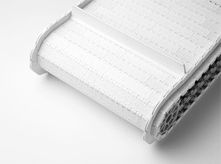
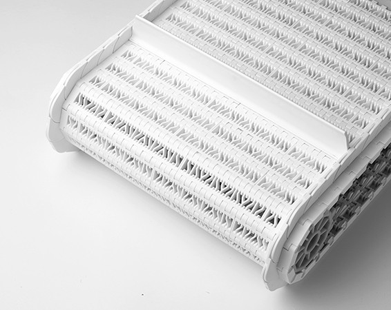
          • poniżej przedstawiamy naszą nową opatentowaną perforowaną taśmę z tworzywa sztucznego, zaprojektowaną do systemów chłodzenia
            Ten rodzaj taśmy z tworzywa sztucznego umożliwia przepływ powietrza, dzięki czemu podczas transportu produkt jest schładzany


        • Przenośnik PA tp z taśmą plastikową
          Rozwiń
          Zwiń


            • stabilna rama wykonana z wytłaczanego profilu aluminiowego, Alloy 6060, zabezpieczona anodyzacją o średniej grubości powłoki 15 mikronów
            • standardowa taśma plastikowy MB bez listew
            • standardowy zespół napędowy, składający się z trójfazowego silnika asynchronicznego o mocy 0,18 kW, sprzężonego z reduktorem ślimakowym ze stałym smarowaniem. Ze względów bezpieczeństwa zespół motoreduktora jest zawsze wyposażony w ogranicznik bezpieczeństwa
            • stała standardowa prędkość przenośnika 4 m/min
            • standardowe napięcie znamionowe silników 400 V / 50 Hz


        • Przenośnik CP TP o zmiennym kierunku z taśmą plastikową
          Rozwiń
          Zwiń


            • stabilna rama wykonana z wytłaczanego profilu aluminiowego, Alloy 6060, zabezpieczona anodyzacją o średniej grubości powłoki 15 mikronów
            • standardowa taśma plastikowy MB z listwami h = 35 mm, skok = 400 mm
            • standardowy zespół napędowy, składający się z trójfazowego silnika asynchronicznego o mocy 0,18 kW, sprzężonego z reduktorem ślimakowym ze stałym smarowaniem. Ze względów bezpieczeństwa zespół motoreduktora jest zawsze wyposażony w ogranicznik bezpieczeństwa
            • stała standardowa prędkość przenośnika 4 m/min
            • standardowe napięcie znamionowe silników 400 V / 50 Hz


        • Przenośnik CPT TP o zmiennym kierunku z taśmą plastikową
          Rozwiń
          Zwiń


            • stabilna rama wykonana z wytłaczanego profilu aluminiowego, Alloy 6060, zabezpieczona anodyzacją o średniej grubości powłoki 15 mikronów
            • standardowa taśma plastikowy MB z listwami h = 35 mm, skok = 400 mm
            • standardowy zespół napędowy, składający się z trójfazowego silnika asynchronicznego o mocy 0,18 kW, sprzężonego z reduktorem ślimakowym ze stałym smarowaniem. Ze względów bezpieczeństwa zespół motoreduktora jest zawsze wyposażony w ogranicznik bezpieczeństwa
            • stała standardowa prędkość przenośnika 4 m/min
            • standardowe napięcie znamionowe silników 400 V / 50 Hz


        • PAR przenośnik z taśmą plastikową
          Rozwiń
          Zwiń


            • zdjęcie powyżej pokazuje przenośnik do zbierania ułożonych w stos płyt z tworzywa sztucznego z jednostki produkcyjnej i przekazywania ich do urządzenia pakującego
            • dwie jednostki robocze mają różne poziomy pracy, dlatego konieczne jest, aby produkt „schodził” do poziomu drugiego urządzenia
            • taśma plastikowa doskonale spełnia funkcję zmiany kierunku


        • Podwójny przenośnik z łukiem 90° z taśmą plastikową
          Rozwiń
          Zwiń


            • zdjęcie powyżej pokazuje przenośnik, który wykonuje zakręt 90° bez przerywania ciągłości
            • zwróć uwagę na dwa różne pasy transportowe, każdy z własnymi regulowanymi panelami bocznymi z tworzywa polyzene
        • Linia przenośników z taśmą plastikową
          Rozwiń
          Zwiń


            • zdjęcie obok pokazuje linię przenośników z różnych punktów odbierania produktów do centrum gromadzenia
            • specyfika taśmy plastikowej, użytej do tych linii polega na możliwości przechodzenia przez łuki 90° bez przerywania ciągłości, gwarantując tym samym doskonałą jakość transportu
            • zwróć uwagę, że regulowane panele boczne z wkładką z tworzywa polyzene są zainstalowane wzdłuż całej drogi
            • linie te są zwykle proponowane do przenoszenia małych pojemników z tworzyw sztucznych


        • Przenośnik liniowy z taśmą plastikową i wbudowanym łukiem 90°
          Rozwiń
          Zwiń


            • zdjęcie powyżej pokazuje linię przenośnika używaną w sektorze opakowań
            • w tej aplikacji przenoszone są małe plastikowe tace, aby w rezultacie otrzymać metalowy produkt osadzony przez linię montażową Robot.
            • na zdjęciu widać również ramę wykonaną ze stali nierdzewnej AISI 304
            • listwy tworzące taśmę wyposażone są we wkładkę antypoślizgową
      • Taśma metalowa
        Rozwiń
        Zwiń


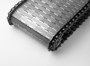
          • taśmy metalowe o różnych powierzchniach: 

            1. gładka – odpowiednia do spawania / wkręcania listew napędowych 
            2. wysoka przyczepność – uniknięcie całkowitego kontaktu produktu z powierzchnią 
            3. wysoka przyczepność i perforacja – w przypadku cieczy do zdekantowania 
            4. siatka – w przypadku dużych ilości cieczy do zdekantowania.


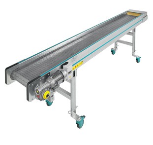
        • Przenośnik PA TM z taśmą metalową
          Rozwiń
          Zwiń


            • stabilna rama wykonana z wytłaczanego profilu aluminiowego, Alloy 6060, zabezpieczona anodyzacją o średniej grubości powłoki 15 mikronów
            • standardowa taśma metalowa MB bez listew
            • standardowy zespół napędowy, składający się z trójfazowego silnika asynchronicznego o mocy 0,37 kW, sprzężonego z reduktorem ślimakowym ze stałym smarowaniem. Ze względów bezpieczeństwa zespół motoreduktora jest zawsze wyposażony w ogranicznik bezpieczeństwa
            • stała standardowa prędkość przenośnika 4 m/min


        • Przenośnik CP TM z taśmą metalową
          Rozwiń
          Zwiń


            • stabilna rama wykonana z wytłaczanego profilu aluminiowego, Alloy 6060, zabezpieczona anodyzacją o średniej grubości powłoki 15 mikronów
            • standardowa taśma metalowa MB z listwami h = 20/30 mm, skok = 400 mm
            • standardowy zespół napędowy, składający się z trójfazowego silnika asynchronicznego o mocy 0,37 kW, sprzężonego z reduktorem ślimakowym ze stałym smarowaniem. Ze względów bezpieczeństwa zespół motoreduktora jest zawsze wyposażony w ogranicznik bezpieczeństwa
            • stała standardowa prędkość przenośnika 4 m/min


        • Przenośnik CPT TM z taśmą metalową
          Rozwiń
          Zwiń


            • stabilna rama wykonana z wytłaczanego profilu aluminiowego, Alloy 6060, zabezpieczona anodyzacją o średniej grubości powłoki 15 mikronów
            • standardowa taśma metalowa MB z listwami h = 20/30 mm, skok = 400 mm
            • standardowy zespół napędowy, składający się z trójfazowego silnika asynchronicznego o mocy 0,37 kW, sprzężonego z reduktorem ślimakowym ze stałym smarowaniem. Ze względów bezpieczeństwa zespół motoreduktora jest zawsze wyposażony w ogranicznik bezpieczeństwa
            • stała standardowa prędkość przenośnika 4 m/min
            • standardowe napięcie znamionowe silników 400 V / 50 Hz


        • Przenośnik PA z taśmą metalową o dużej wytrzymałości
          Rozwiń
          Zwiń


            • zdjęcie obok pokazuje przenośnik PA wyposażony w ciężką metalową taśmę, używany do przenoszenia materiałów plastikowych lub metalowych w trudnych warunkach, takich jak odlewnie, cięcie, itp.


        • Przenośnik MB z taśmą metalową o dużej wytrzymałości
          Rozwiń
          Zwiń


            • zdjęcie powyżej pokazuje przenośnik MB tm wyposażony w wytrzymałą metalową tasmę
            • uwaga: listwy przenośnika zostały przyspawane do tasmy
            • ramy konstrukcyjne przenośników, w których mocowana jest taśma metalowa o dużej wytrzymałości, są wykonane z wytrzymałej spawanej blachy o grubości 3 mm


        • Przenośnik pionowy EV z metalową taśmą o dużej wytrzymałości
          Rozwiń
          Zwiń


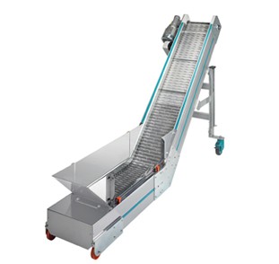
            • zdjęcie powyżej pokazuje przenośnik EV wyposażony w metalową taśmę o dużej wytrzymałości, używaną do podnoszenia wyrobów metalowych (śrub, nitów, wkładek, itp.)
            • produkt jest rozładowywany do leja i podnoszony zgodnie z potrzebami linii montażowej, znajdującej się poniżej
            • lej jest nieduży, ale w razie potrzeby dostępny jest w większym rozmiarze


        • System do odbierania, przenoszenia i oddzielania produktów ze stopu
          Rozwiń
          Zwiń


            • na zdjęciu powyżej pokazano system składający się z przenośnika MB z taśmą metalową, w komplecie ze zbiornikiem, w którym osadzone są złącza PVC
            • produkt jest podnoszony i rozładowywany na przenośniku PA, zainstalowanym w położeniu prostopadłym. To rozwiązanie pozwala na prostopadłe wyrównanie produktu
            • wysokość i skok listew przyspawanych do taśmy wraz z prędkością przenośnika określają przepływ łączników, które mają być przesłane do jednostki montażowej za pomocą prostopadłego przenośnika PA


        • Przenośnik CP z metalową taśmą o dużej wytrzymałości
          Rozwiń
          Zwiń


            • zdjęcie obok pokazuje aplikację szeroko stosowaną w różnych sektorach produkcyjnych, począwszy od tworzyw sztucznych, przez odlewnictwo wyrobów ze stopów, sektor odzyskiwania tworzyw sztucznych, odlewnie stopów i żeliwa, po stolarstwo
            • dolna płaska sekcja umożliwia instalację tego przenośnika wewnątrz przedziału maszyny roboczej, gdzie znajduje się zsyp rozładunkowy lub przed przenośnikiem, obecnym w większości jednostek produkcyjnych
            • przenośniki te są bardzo wytrzymałe i rzadko wymagają naprawy lub konserwacji


        • Separator z bębnem z rolkami metalowymi
          Rozwiń
          Zwiń


            • zdjęcie powyżej pokazuje wersję separatora SR, którą zalecamy do oddzielania wlewków / produktów wykonanych z materiału zamak / aluminium lub materiału metalicznego
            • to rozwiązanie jest szeroko stosowane w dziedzinie odlewania kokilowego. Rolki bębna wykonane są z rury ze stali nierdzewnej, jeśli jest to konieczne, lub z ocynkowanej rury stalowej. W tym rozwiązaniu rolki zamocowane są na stałe i nie obracają się wokół własnej osi podczas obrotu bębna
            • odległość między rolkami regulowana jest ręcznie
            • zwróć uwagę na izolację separatora niezbędną do zmniejszenia hałasu do minimum


  • Belt conveyors
    Rozwiń
    Zwiń

      Producing individual solutions, devices and systems for every application and need in the field of industrial conveying: this is how MB Conveyors fulfills its mission.

    • Standard belt conveyors
      Rozwiń
      Zwiń
      • PA – standard flat belt conveyor
        Rozwiń
        Zwiń


          • Anodized ALU profile structure (thickness 15 Microns) Alloy 6060
          • Standard cut-proof, oil-proof belt with smooth green Polyurethane covering (ref. Pantone 320); vulcanized belt joint
          • minimum and maximum thermal resistance of the tape: -10°C to + 90°C
          • standard drive unit consisting of a 0.12 kW, three-phase, asynchronous motor coupled to a worm gear reducer with permanent lubrication
          • constant standard conveyor speed 3 m/min
          • conveyor complete with Siemens Start / Stop switch / engine switch, with 5 m cable and 4P CE plug (3 phases + ground)
          • standard motor supply voltage 400 V / 50 Hz


      • PAR – conveyor with adjustable flat top
        Rozwiń
        Zwiń


          • Anodized ALU profile structure (thickness 15 Microns) Alloy 6060
          • Standard cut and oil resistant belt with high-adhesion green PVC coating (Pantone Ref. 320); vulcanized belt joint
          • Minimum and maximum thermal resistance of the belt: -10°C to + 60°C
          • standard drive unit consisting of a 0.12 kW, three-phase, asynchronous motor coupled to a worm gear reducer with permanent lubrication
          • constant standard conveyor speed 3 m/min
          • conveyor complete with Siemens Start / Stop switch / motor switch, with 5 m cable and 4P CE plug (3 phases + earth)
          • standard motor supply voltage 400 V / 50 Hz


      • PA Robot – robot-assisted flat conveyor
        Rozwiń
        Zwiń


          • The photo above shows the PA conveyor with polycarbonate covers.
            The PA conveyor model (cross-section 110×30 mm) was found to be the most suitable for this purpose due to:
            – its strong, robust construction;
            – the ability to install/remove side safety panels;
            – the ability to install control photocells above and inside the side panels;
            – the ease of installing the robot’s protective structure.


      • PA 180 – flat conveyor for heavy loads
        Rozwiń
        Zwiń


          • Anodized ALU profile structure (thickness 15 Microns) Alloy 6060
          • Standard cut and oil resistant belt with black polyurethane coating; vulcanized belt joint
          • minimum and maximum thermal resistance of the tape: -10°C to + 90°C
          • a standard drive unit consisting of a three-phase asynchronous motor with a power appropriate to the dimensions and required power, coupled with a worm gear reducer with permanent lubrication
          • constant standard conveyor speed 5 m/min
          • conveyor complete with Siemens Start / Stop switch / engine switch, with 5 m cable and 4P CE plug (3 phases + ground)
          • standard motor supply voltage 400 V / 50 Hz


      • Curves
        Rozwiń
        Zwiń


          • The photo above shows the F.D.A. version of the 90° bend conveyor with parallel rollers.
          • In this solution, all structural parts of the conveyor are made of 304 AISI stainless steel
          • conveyor suitable for transporting food and pharmaceutical products
          • the conveyor belt, in this case blue as requested by the customer, is fully compliant with FDA standards.


      • N-TR – adjustable incline conveyor
        Rozwiń
        Zwiń

          • Anodized ALU profile structure (thickness 15 Microns) Alloy 6060
          • Standard, cut- and oil-resistant belt with a smooth green polyurethane coating (Pantone 320); with welded strips with a height of h=30 mm every 400 mm; vulcanized belt joint
          • minimum and maximum thermal resistance of the belt: -10°C to + 90°C
          • standard drive unit consisting of a 0.12 kW, three-phase, asynchronous motor coupled to a worm gear reducer with permanent lubrication
          • constant standard conveyor speed 3 m/min
          • conveyor complete with Siemens Start / Stop switch / motor switch, with 5 m cable and 4P CE plug (3 phases + earth)
          • standard motor supply voltage 400 V / 50 Hz


      • N-CPR – conveyor with direction change
        Rozwiń
        Zwiń


          • Anodized ALU profile structure (thickness 15 Microns) Alloy 6060
          • Standard, cut- and oil-resistant belt with a smooth green polyurethane coating (Pantone 320); with welded strips with a height of h=30 mm every 400 mm; vulcanized belt joint
          • minimum and maximum thermal resistance of the belt: -10°C to + 90°C
          • standard drive unit consisting of a 0.12 kW, three-phase, asynchronous motor coupled to a worm gear reducer with permanent lubrication
          • constant standard conveyor speed 3 m/min
          • conveyor complete with Siemens Start / Stop switch / motor switch, with 5 m cable and 4P CE plug (3 phases + earth)
          • standard motor supply voltage 400 V / 50 Hz
          • On request, the Easy Line version is available (photo below) with a simplified design of the supporting legs, which allows for a reduction of approximately 15% of the final price of the conveyors


          Easy Line version

      • N-CPTR – conveyor with direction change
        Rozwiń
        Zwiń


          • Anodized ALU profile structure (thickness 15 Microns) Alloy 6060
          • Standard, cut- and oil-resistant belt with a smooth green polyurethane coating (Pantone 320); with welded strips with a height of h=30 mm every 400 mm; vulcanized belt joint
          • minimum and maximum thermal resistance of the tape: -10°C to + 90°C
          • standard drive unit consisting of a 0.12 kW, three-phase, asynchronous motor coupled to a worm gear reducer with permanent lubrication
          • constant standard conveyor speed 3 m/min
          • conveyor complete with Siemens Start / Stop switch / motor switch, with 5 m cable and 4P CE plug (3 phases + earth)
          • standard motor supply voltage 400 V / 50 Hz
          • On request, the Easy Line version is available with a simplified design of the supporting legs, which allows for a reduction of approximately 15% of the final price of the conveyors


      • N-PA – flat conveyor Easy Line
        Rozwiń
        Zwiń


          • Anodized ALU profile structure (thickness 15 Microns) Alloy 6060
          • Standard cut-proof, oil-proof belt with smooth green Polyurethane covering (ref. Pantone 320); vulcanized belt joint
          • minimum and maximum thermal resistance of the tape: -10°C to + 90°C
          • standard drive unit consisting of a 0.12 kW, three-phase, asynchronous motor coupled to a worm gear reducer with permanent lubrication
          • constant standard conveyor speed 3 m/min
          • conveyor complete with Siemens Start / Stop switch / motor switch, with 5 m cable and 4P CE plug (3 phases + earth)
          • standard motor supply voltage 400 V / 50 Hz


    • Elevators
      Rozwiń
      Zwiń
      • Belt elevator EV 600
        Rozwiń
        Zwiń


          • anodized ALU profile structure (thickness 15 Microns) Alloy 6060
          • standard, cut- and oil-resistant belt with a smooth green polyurethane coating (Pantone 320); with welded strips with a height of h=30 mm every 150 mm; vulcanized belt joint
          • minimum and maximum thermal resistance of the tape: -10°C to + 90°C
          • standard drive unit consisting of a 0.18 kW, three-phase, asynchronous motor coupled to a worm gear reducer with permanent lubrication
          • constant standard conveyor speed 12 m/min
          • conveyor complete with Siemens Start / Stop switch / motor switch, with 5 m cable and 4P CE plug (3 phases + earth)
          • standard motor supply voltage 400 V / 50 Hz


      • Belt elevator EV 800 – EV 1000
        Rozwiń
        Zwiń


          • anodized ALU profile structure (thickness 15 Microns) Alloy 6060
          • standard, cut- and oil-resistant belt with a smooth green polyurethane coating (Pantone 320); with welded strips with a height of h=30/50 mm every 150 mm; vulcanized belt joint
          • minimum and maximum thermal resistance of the tape: -10°C to + 90°C
          • standard drive unit consisting of a 0.18 kW, three-phase, asynchronous motor coupled to a worm gear reducer with permanent lubrication
          • constant standard conveyor speed 12 m/min
          • conveyor complete with Siemens Start / Stop switch / motor switch, with 5 m cable and 4P CE plug (3 phases + earth)
          • standard motor supply voltage 400 V / 50 Hz


    • Conveyor belts with cooling
      Rozwiń
      Zwiń

        Sometimes we have to deal with production that requires cooling of products while they are transported on conveyor belts.

        For such cases, we offer our reliable MB Conveyors with various cooling systems.

      • Cooling conveying system with helical fans
        Rozwiń
        Zwiń


          • The combination of a mesh conveyor belt and the airflow generated by the installed electric fans provides ideal conditions for cooling the product during transport.
          • The tunnel in which the electric fans are installed is made of polycarbonate with an aluminum support frame
          • Conveyor speed control is the third important element that complements and improves this combination. The MB control panel is typically used for this function.


      • Cooling system with radial fans
        Rozwiń
        Zwiń


          • The photo above shows a CPT conveyor made of PA 180 aluminum profile and with a plastic belt
          • The special shape of the internal structure creates a constant air flow and a pressure head that hits the product as it moves along the conveyor
          • Note the polycarbonate tunnel installed to protect the transported product


      • Water-cooled conveying system
        Rozwiń
        Zwiń


          • The photo above shows a system in which the cooling element is water
          • The transported product is immersed in water along the entire length of the tank from the upper PA conveyor
          • At the end of the journey, the product is collected by the upper part of the CP conveyor and removed from the tank
          • Flat conveyor and CP speeds are adjustable (see MB control panels)


    • Separation
      Rozwiń
      Zwiń
      • N-CPST – conveyor with paddle separator
        Rozwiń
        Zwiń


          • anodized ALU profile structure (thickness 15 Microns) Alloy 6060
          • Standard cut and oil resistant belt with high-adhesion green PVC coating (Pantone Ref. 320); vulcanized belt joint
          • Minimum and maximum thermal resistance of the belt: -10°C to + 60°C
          • standard drive unit consisting of a 0.12 kW, three-phase, asynchronous motor coupled to a worm gear reducer with permanent lubrication
          • constant standard conveyor speed 3 m/min
          • conveyor complete with Siemens Start / Stop switch / motor switch, with 5 m cable and 4P CE plug (3 phases + earth)
          • standard motor supply voltage 400 V / 50 Hz
          • On request, the Easy Line version is available with a simplified design of the supporting legs (photo below), which allows for a reduction of approximately 15% of the final price of the conveyors


          Easy Line version


      • SR – independent separator with roller drum
        Rozwiń
        Zwiń


          • separator with a rotating drum consisting of 24 PVC rollers with a diameter of 50 mm and a length of 800 mm (the distance between the rollers can be adjusted MANUALLY)
          • each separator has its own inverter to regulate the drum rotation speed; possible adjustment range: minimum 4 rpm, maximum 20 rpm
          • the SR separator has a manual adjustment of the distance between the rollers
          • the drum frame is supported by two threaded rods that allow the drum tilt to be adjusted on both sides
          • finding the right ratio of the drum rotational speed to the slight counter-inclination allows for effective separation of the product from the sprue
          • in standard separators, the roller drum can be replaced with a perforated drum
          • motor supply voltage: 220 V / 50 Hz, single-phase


      • SM – independent separator with perforated drum
        Rozwiń
        Zwiń


          • separator with a perforated rotating drum made of AISI 304 stainless steel sheet, usually with small anti-slip tubes
          • each separator has its own inverter to regulate the drum rotation speed; possible adjustment range: minimum 4 rpm, maximum 20 rpm
          • in the SM separator, the diameter of the holes and the need to weld anti-slip pipes depend on the shape of the product and the sprue
          • the drum frame is supported by two threaded rods that allow the drum tilt to be adjusted on both sides
          • finding the right ratio of the drum rotational speed to the slight counter-inclination allows for effective separation of the product from the sprue
          • motor supply voltage: 220 V / 50 Hz, single-phase


      • FSRV – spiral separator with base
        Rozwiń
        Zwiń


          • separator with independent base on the ground (for positioning in front of the conveyor only when necessary)
          • separator chute made of polished AISI 304 stainless steel sheet
          • gearbox assembly located on the right side, power 0.09 kW, with torque limiter
          • rotational speed of the distribution roller: 70 rpm
          • starting and stopping the separator using a Siemens motor switch
          • standard motor supply voltage 400 V/50 Hz


      • N-SRS – single roller separators
        Rozwiń
        Zwiń


          • three models are available:
            1 – N-SRS 1 model for a conveyor with a working width of 240 mm
            2 – N-SRS 2 model for a conveyor with a working width of 340 mm
            3 – N-SRS 3 model for a conveyor with a working width of 440 mm
          • this separator is designed for installation on N-CPR and N-CPTR conveyors
          • the transfer of motion from the conveyor to the single separator roller is carried out by means of a Pu belt
          • thanks to the elasticity of the belt, the distance between the separator roller and the conveyor can be adjusted from a minimum of 5 mm to a maximum of 20 mm
          • the conveyor on which the N-SRS separator is installed must have a belt with slats with a maximum height of 20 mm


          N-SRS separator with N-CPR conveyor


      • N-FSRV – spiral separators
        Rozwiń
        Zwiń


          • three models of N-FSRV separators are available:
            1 – N-FSRV 1 model for a conveyor with a working width of 240 mm
            2 – N-FSRV 2 model for a conveyor with a working width of 340 mm
            3 – N-FSRV 3 model for a conveyor with a working width of 440 mm
          • the N-FSRV sprue separator is installed directly on the conveyor, from which the spiral obtains a rotary motion
          • the transfer of motion from the conveyor to the spiral roller is accomplished via a PU belt. For safety reasons, the belt is sufficiently tensioned to allow rotation. If the slightest obstacle occurs, the spiral roller stops.


          N-FSRV with N-CPR conveyor


    • Metal detectors
      Rozwiń
      Zwiń

        Metal detectors ensure the cleanliness of the material and free it from metallic impurities.

      • MD Plate Metal Detector
        Rozwiń
        Zwiń


          The figure above shows a plate metal detector placed inside the N-CPR conveyor to detect metal contaminants as the material is transferred from the forming device to the mill.

          The plate metal detector is also ideal for applications outside of injection molding where there is a near-continuous flow of material that is usually well distributed on the conveyor.


          CP complete with metal detector


      • MD Tunnel Metal Detector
        Rozwiń
        Zwiń


          The figure below shows a tunnel metal detector installed on an MB conveyor to detect metallic contaminants contained in large masses of material and/or large-sized products. These solutions are commonly used in the field of plastics recovery..


          MB 180 complete with tunnel metal detector


      • MD magnetic roller
        Rozwiń
        Zwiń


          The magnetic roller is only proposed when the detected metallic contaminants are ferrous and therefore sensitive to the magnetic field.

          The roller consists of a series of sector magnets attached to each other and is installed as a drive roller.

          Ferrous impurities captured by the magnetic field do not fall into the granulator inlet, but are carried outside and discharged into a chute intended for this purpose.


    • Storage
      Rozwiń
      Zwiń
      • TVC – rotating tables
        Rozwiń
        Zwiń


          • rotating tables start with a basic model called TV, and then, depending on their application, are divided into:
            – rotating tables for containers, which are the TVC model
            – rotating tables for bags, which are the TVS model
          • technical features of the basic model of the rotating table called TV:
            A 3 mm thick plate made of AISI 430 steel on which the tables rest
          • the TVC (turntable for containers) and TVS (turntable for bags) functions are defined in the sales offer. The model and features depend on the type and dimensions of the container.
          • the power supply voltage of the motor of standard rotary tables is 400 V / 50 Hz


      • TVS – rotating tables
        Rozwiń
        Zwiń


          • rotating tables start with a basic model called TV, and then, depending on their application, are divided into:
            – rotating tables for containers, which are the TVC model
            – rotating tables for bags, which are the TVS model
          • Technical features of the basic model of the TV rotating table:
            A 3 mm thick AISI 430 plate on which the tables rest
          • the TVC (turntable for containers) and TVS (turntable for bags) functions are defined in the sales offer. The model and features depend on the type and dimensions of the container.
          • the power supply voltage of the motor of standard rotary tables is 400 V / 50 Hz


      • DUCK – dispenser
        Rozwiń
        Zwiń

          • the DUCK dispenser can operate using two different methods that are not compatible with each other:
            – using a voltage-free A/C signal from the injection molding machine in each molding cycle
            – setting a fill time for each container
          • the DUCK dispenser chute can rotate 360° and can guide the product to any point on its path
          • capacity: does not exceed 2 kg for each product
          • installed engine power for chute rotation: 0.06 kW
          • standard motor supply voltage: 400 V / 50 Hz


      • CAR – storage system
        Rozwiń
        Zwiń


          • the photo above shows a system for storing products in containers on a structure with two flat conveyors and a cross beam
          • the system is complemented by a dust cover made of a shaped aluminum profile with polycarbonate plates
          • pay attention to the loading conveyor which, working synchronously with the system, transfers and unloads the product into containers


      • CAV – vertical storage system
        Rozwiń
        Zwiń


          • the drawing above shows a vertical carousel with two floors with a vertical side conveyor
          • the upper conveyor is filled with empty containers when the container is filled, the elevator transfers it to the lower conveyor
          • the vertical movement area of ​​the elevator is equipped with a special protective device


      • Storage system Filling
        Rozwiń
        Zwiń


          • the photo above shows the CPT conveyor for collecting and transferring the product to the PA distributor conveyor for storage in two containers
          • the operating logic includes counting the formed elements to be stored in the container
          • technical and dimensional features of the system are determined from time to time, depending on the needs
          • the drawing below shows the application shown above
          • a characteristic feature of this system is the constant movement of the PA conveyor-distributor along its longitudinal axis
          • this particular feature allows the container to be filled evenly, avoiding central accumulation


      • Storage system Weighing
        Rozwiń
        Zwiń


          • the photo shows a group consisting of a conveyor for receiving and transferring products, a hopper for weighing them for storing them in containers with high counting accuracy and a rotating table for sequential filling of 7 containers
          • this system allows for very precise storage of products in containers and significant filling autonomy outside the injection molding machine


      • MI Vertical Mixer
        Rozwiń
        Zwiń


          • the MI vertical mixer is a solution that has always been used for mixing plastic granulates
          • the vertical mixer consists of an external frame made of painted sheet metal and an internal screw inside the tube for mixing the contents
          • the material to be mixed is fed into the hopper, the screw picks it up from the bottom and carries it upwards, releasing it at the top, distributing it inside the mixer body with a 360° radius. After about 15/20 minutes, the material is perfectly mixed
          • the mixer power supply includes a control panel built in accordance with EEC standards, with Start and Stop functions and run and stop time settings
          • the inspection hatches of the screw conveyor and mixer are protected by safety microswitches


      • MI1 mixer
        Rozwiń
        Zwiń


          • the photo above shows a vertical mixer for mixing small quantities of product or, as is often the case, for molding tests or materials testing.
          • It is therefore suitable when product batches are not very large
          • the mixing principle remains unchanged: on request, the screw is closed in the pipe, the material is fed from above. The mixed product is usually taken up via a suction port and fed into one of the two conical side pipes of the container
          • the valve for quick emptying and/or cleaning inside the mixer tank and the tank cover is protected by microswitches


    • Conveyors with plastic and metal belts
      Rozwiń
      Zwiń
      • Plastic belt
        Rozwiń
        Zwiń


          • the side edge of the container does not open even when the blade is rotating on the drive wheels
          • the contact surface of the plastic belt has slightly increased adhesion
          • reinforced PP plastic belt, color RAL 9002
          • operating temperature + 1°C to approximately 130°C
          • standard strip: h = 35 mm modular, min. pitch 25 mm
          • possibility of using special strips depending on customer requirements
          • A = 75 to 775 mm (100 mm stroke)
          • below we present our new patented perforated plastic tape designed for cooling systems
            This type of plastic tape allows air to flow through, keeping the product cool during transport


        • PA TP conveyor with plastic belt
          Rozwiń
          Zwiń


            • anodized ALU profile structure (thickness 15 Microns) Alloy 6060
            • standard MB plastic belt without strips
            • the standard drive unit consists of a 0.18 kW three-phase asynchronous motor coupled to a permanently lubricated worm gear reducer. For safety reasons, the gear reducer unit is always equipped with a safety limiter
            • constant standard conveyor speed 4 m/min
            • standard rated voltage of motors 400 V / 50 Hz


        • CP TP conveyor with direction change and plastic belt
          Rozwiń
          Zwiń


            • anodized ALU profile structure (thickness 15 Microns) Alloy 6060
            • standard MB plastic belt with strips h = 35 mm, pitch = 400 mm
            • the standard drive unit consists of a 0.18 kW three-phase asynchronous motor coupled to a permanently lubricated worm gear reducer. For safety reasons, the gear reducer unit is always equipped with a safety limiter
            • constant standard conveyor speed 4 m/min
            • standard rated voltage of motors 400 V / 50 Hz


        • CPT TP conveyor with direction change and plastic belt
          Rozwiń
          Zwiń


            • anodized ALU profile structure (thickness 15 Microns) Alloy 6060
            • standard MB plastic belt with strips h = 35 mm, pitch = 400 mm
            • the standard drive unit consists of a 0.18 kW three-phase asynchronous motor coupled to a permanently lubricated worm gear reducer. For safety reasons, the gear reducer unit is always equipped with a safety limiter
            • constant standard conveyor speed 4 m/min
            • standard rated voltage of motors 400 V / 50 Hz


        • PAR conveyor with plastic belt
          Rozwiń
          Zwiń


            • the photo above shows a conveyor for collecting stacked plastic sheets from the production unit and transferring them to the packaging machine
            • two working units have different working levels, so it is necessary for the product to „come down” to the level of the second device
            • plastic belt perfectly fulfills the function of changing direction


        • Double conveyor with a 90° bend and plastic belt
          Rozwiń
          Zwiń


            • the photo above shows a conveyor that makes a 90° turn without breaking the continuity
            • note the two different carrying straps, each with its own adjustable polyzene side panels
        • Line of plastic belt conveyor
          Rozwiń
          Zwiń


            • the photo above shows a line of conveyors moving from various product collection points to the collection center
            • the specificity of the plastic belt used for these lines is the ability to pass through 90° bends without breaking the continuity, thus guaranteeing excellent transport quality
            • note that adjustable side panels with polyzene inserts are installed along the entire length of the road
            • these lines are usually designed for transporting small plastic containers


        • Conveyor line with plastic belt and built-in 90° bend
          Rozwiń
          Zwiń


            • the photo above shows a conveyor line used in the packaging sector
            • in this application, small plastic trays are transferred to result in a metal product being deposited by the Robot assembly line
            • the photo also shows a frame made of AISI 304 stainless steel
            • the strips forming the belt are equipped with an anti-slip insert
      • Metal belt
        Rozwiń
        Zwiń


          • metal belt with different surfaces:

            1. smooth – suitable for welding/screwing drive strips
            2. high grip (standard) – avoids complete contact of the product with the conveying surface
            3. high grip perforated – when small amount of liquid needs to be drained
            4. mesh – when significant amount of liquid needs to be drained


        • PA TM conveyor with metal belt
          Rozwiń
          Zwiń


            • anodized ALU profile structure (thickness 15 Microns) Alloy 6060
            • standard MB metal belt without strips
            • the standard drive unit consists of a 0.37 kW three-phase asynchronous motor coupled to a permanently lubricated worm gear reducer. For safety reasons, the gear reducer unit is always equipped with a safety limiter
            • constant standard conveyor speed 4 m/min


        • CP TM conveyor with metal belt
          Rozwiń
          Zwiń


            • anodized ALU profile structure (thickness 15 Microns) Alloy 6060
            • standard MB metal belt with strips h = 20/30 mm, pitch = 400 mm
            • the standard drive unit consists of a 0.37 kW three-phase asynchronous motor coupled to a permanently lubricated worm gear reducer. For safety reasons, the gear reducer unit is always equipped with a safety limiter
            • constant standard conveyor speed 4 m/min


        • CPT TM conveyor with metal belt
          Rozwiń
          Zwiń


            • anodized ALU profile structure (thickness 15 Microns) Alloy 6060
            • standard MB metal belt with strips h = 20/30 mm, pitch = 400 mm
            • the standard drive unit consists of a 0.37 kW three-phase asynchronous motor coupled to a permanently lubricated worm gear reducer. For safety reasons, the gear reducer unit is always equipped with a safety limiter
            • constant standard conveyor speed 4 m/min
            • standard rated voltage of motors 400 V / 50 Hz


        • PA conveyor with high-strength metal belt
          Rozwiń
          Zwiń


            • The photo above shows a PA conveyor equipped with a heavy metal belt, used to convey plastic or metal materials in harsh environments such as foundries, cutting, etc.


        • MB conveyor with high-strength metal belt
          Rozwiń
          Zwiń


            • the photo above shows the MB tm conveyor equipped with a durable metal belt
            • note: the conveyor slats are welded to the belt
            • the structural frames of the conveyors, in which the high-strength metal belt is mounted, are made of durable, welded sheet metal with a thickness of 3 mm


        • EV belt elevator with high-strength metal belt
          Rozwiń
          Zwiń


            • the photo above shows an EV conveyor equipped with a high-strength metal belt used to lift metal products (screws, rivets, inserts, etc.)
            • the product is unloaded into a hopper and lifted according to the needs of the assembly line below
            • the hopper is small, but if necessary it is available in a larger size


        • System for receiving, conveying and separating alloy products
          Rozwiń
          Zwiń


            • the photo above shows a system consisting of an MB conveyor with a metal belt, complete with a tank in which PVC connectors are mounted
            • the product is lifted and unloaded onto the PA conveyor, installed in a perpendicular position. This solution allows for perpendicular product alignment
            • the height and pitch of the strips welded to the belt, together with the conveyor speed, determine the flow of fasteners to be sent to the assembly unit via the perpendicular PA conveyor


        • CP conveyor with high-strength metal belt
          Rozwiń
          Zwiń


            • the photo above shows an application widely used in various production sectors, from plastics, through the foundry of alloy products, the plastics recovery sector, alloy and iron foundries, to carpentry
            • the lower flat section allows the installation of this conveyor inside the working machine compartment where the unloading chute is located or in front of the conveyor present in most production units
            • these conveyors are very durable and rarely require repair or maintenance


        • Drum separator with metal rollers
          Rozwiń
          Zwiń


            • the photo above shows the SR separator version that we recommend for separating ingots/products made of zamak/aluminum or metallic material
            • this solution is widely used in the field of die casting. The drum rollers are made of stainless steel pipe, if necessary, or galvanized steel pipe. In this solution, the rollers are permanently mounted and do not rotate around their own axis when the drum rotates
            • the distance between the rollers is adjusted manually
            • pay attention to the separator insulation necessary to reduce noise to a minimum


  • Förderbänder
    Rozwiń
    Zwiń

      Die Herstellung individueller Lösungen, Geräte und Systeme für jede Anwendung und jeden Bedarf im Bereich der industriellen Fördertechnik: So erfüllt MB Conveyors seine Mission.

    • Standard-Bandförderer
      Rozwiń
      Zwiń
      • PA – Standard-Flachbandförderer
        Rozwiń
        Zwiń


          • Struktur aus ALU-eloxiertem Profil (Dicke 15 Mikron) Legierung 6060
          • Schnitt- und ölfester Standardfördergurt mit glatter Oberfläche aus grünem Polyurethan (Pantone 320), vulkanisierte Fördergurtverbindung
          • Minimaler und maximaler Wärmewiderstand des Bandes: -10°C bis +90°C
          • Standardantriebseinheit bestehend aus einem 0,12 kW, dreiphasigen Asynchronmotor, der mit einem Schneckengetriebe mit Dauerschmierung gekoppelt ist
          • Konstante Standard-Förderbandgeschwindigkeit 3 ​​m/min
          • Förderband komplett mit Siemens Start-/Stoppschalter/Motorschalter, mit 5 m Kabel und 4P CE-Stecker (3 Phasen + Erde)
          • Standardmäßige Motorversorgungsspannung 400 V / 50 Hz


      • PAR – Förderband mit verstellbarer flacher Oberseite
        Rozwiń
        Zwiń


          • Struktur aus ALU-eloxiertem Profil (Dicke 15 Mikron) Legierung 6060
          • Standardmäßiges schnitt- und ölbeständiges Band mit hochhaftender grüner PVC-Beschichtung (Pantone Ref. 320); vulkanisierte Bandverbindung
          • Minimaler und maximaler Wärmewiderstand des Bandes: -10 °C bis +60 °C
          • Standardantriebseinheit bestehend aus einem 0,12 kW, dreiphasigen Asynchronmotor, der mit einem Schneckengetriebe mit Dauerschmierung gekoppelt ist
          • Konstante Standard-Förderbandgeschwindigkeit 3 ​​m/min
          • Förderband komplett mit Siemens Start-/Stoppschalter/Motorschalter, mit 5 m Kabel und 4P CE-Stecker (3 Phasen + Erde)
          • Standardmäßige Motorversorgungsspannung 400 V / 50 Hz


      • PA Robot – Flachförderer für die Roboterbedienung
        Rozwiń
        Zwiń


          • Das Foto oben zeigt das PA-Förderband mit Polycarbonat-Abdeckungen.
            Das PA-Förderbandmodell (Querschnitt 110 x 30 mm) erwies sich aufgrund folgender Merkmale als am besten geeignet:
            – seine robuste Konstruktion;
            – die Möglichkeit, seitliche Sicherheitspaneele anzubringen/abzunehmen;
            – die Möglichkeit, Lichtschranken oberhalb und innerhalb der Seitenpaneele zu installieren;
            – die einfache Montage der Schutzstruktur des Roboters.


      • PA 180 – Flachförderer für schwere Lasten
        Rozwiń
        Zwiń


          • Struktur aus ALU-eloxiertem Profil (Dicke 15 Mikron) Legierung 6060
          • Standardmäßiges schnitt- und ölbeständiges Band mit schwarzer Polyurethanbeschichtung; vulkanisierte Bandverbindung
          • Minimaler und maximaler Wärmewiderstand des Bandes: -10°C bis +90°C
          • eine Standardantriebseinheit bestehend aus einem dreiphasigen Asynchronmotor mit einer den Abmessungen und der benötigten Leistung entsprechenden Leistung, gekoppelt mit einem Schneckengetriebe mit Dauerschmierung
          • Konstante Standard-Förderbandgeschwindigkeit 5 m/min
          • Förderband komplett mit Siemens Start-/Stoppschalter/Motorschalter, mit 5 m Kabel und 4P CE-Stecker (3 Phasen + Erde)
          • Standardmäßige Motorversorgungsspannung 400 V / 50 Hz


      • Kurvenförderer
        Rozwiń
        Zwiń


          • Das obige Foto zeigt die FDA-Version des 90°-Biegeförderers mit parallelen Rollen.
          • Bei dieser Lösung sind alle Strukturteile des Förderbandes aus Edelstahl 304 AISI gefertigt.
          • Förderband geeignet für den Transport von Lebensmitteln und pharmazeutischen Produkten
          • Das Förderband, in diesem Fall blau wie vom Kunden gewünscht, entspricht vollständig den FDA-Standards.


      • N-TR – Förderband mit einstellbarer Neigung
        Rozwiń
        Zwiń

          • Struktur aus ALU-eloxiertem Profil (Dicke 15 Mikron) Legierung 6060
          • Standardmäßiges, schnitt- und ölbeständiges Band mit glatter, grüner Polyurethanbeschichtung (Pantone 320); mit verschweißten Streifen (Höhe h = 30 mm, Abstand 400 mm); vulkanisierte Bandverbindung
          • Minimaler und maximaler Wärmewiderstand des Bandes: -10°C bis +90°C
          • Standardantriebseinheit bestehend aus einem 0,12 kW, dreiphasigen Asynchronmotor, der mit einem Schneckengetriebe mit Dauerschmierung gekoppelt ist
          • Konstante Standard-Förderbandgeschwindigkeit 3 ​​m/min
          • Förderband komplett mit Siemens Start-/Stoppschalter/Motorschalter, mit 5 m Kabel und 4P CE-Stecker (3 Phasen + Erde)
          • Standardmäßige Motorversorgungsspannung 400 V / 50 Hz


      • N-CPR – Reversierbares Förderband
        Rozwiń
        Zwiń


          • Struktur aus ALU-eloxiertem Profil (Dicke 15 Mikron) Legierung 6060
          • Standardmäßiges, schnitt- und ölbeständiges Band mit glatter, grüner Polyurethanbeschichtung (Pantone 320); mit verschweißten Streifen (Höhe h = 30 mm, Abstand 400 mm); vulkanisierte Bandverbindung
          • Minimaler und maximaler Wärmewiderstand des Bandes: -10°C bis +90°C
          • Standardantriebseinheit bestehend aus einem 0,12 kW, dreiphasigen Asynchronmotor, der mit einem Schneckengetriebe mit Dauerschmierung gekoppelt ist
          • Konstante Standard-Förderbandgeschwindigkeit 3 ​​m/min
          • Förderband komplett mit Siemens Start-/Stoppschalter/Motorschalter, mit 5 m Kabel und 4P CE-Stecker (3 Phasen + Erde)
          • Standardmäßige Motorversorgungsspannung 400 V / 50 Hz
          • Auf Anfrage ist die Easy Line-Version (siehe Foto unten) mit einer vereinfachten Konstruktion der Stützbeine erhältlich, wodurch der Endpreis der Förderbänder um ca. 15 % reduziert werden kann.


          Easy Line-Version

      • N-CPTR – Reversierbares Förderband
        Rozwiń
        Zwiń


          • Struktur aus ALU-eloxiertem Profil (Dicke 15 Mikron) Legierung 6060
          • Standardmäßiges, schnitt- und ölbeständiges Band mit glatter, grüner Polyurethanbeschichtung (Pantone 320); mit verschweißten Streifen (Höhe h = 30 mm, Abstand 400 mm); vulkanisierte Bandverbindung
          • Minimaler und maximaler Wärmewiderstand des Bandes: -10°C bis +90°C
          • Standardantriebseinheit bestehend aus einem 0,12 kW, dreiphasigen Asynchronmotor, der mit einem Schneckengetriebe mit Dauerschmierung gekoppelt ist
          • Konstante Standard-Förderbandgeschwindigkeit 3 ​​m/min
          • Förderband komplett mit Siemens Start-/Stoppschalter/Motorschalter, mit 5 m Kabel und 4P CE-Stecker (3 Phasen + Erde)
          • Standardmäßige Motorversorgungsspannung 400 V / 50 Hz
          • Auf Anfrage ist die Easy Line-Version mit einer vereinfachten Konstruktion der Stützbeine erhältlich, wodurch der Endpreis der Förderbänder um ca. 15 % reduziert werden kann.


      • N-PA – Easy Line Flachförderband
        Rozwiń
        Zwiń


          • Struktur aus ALU-eloxiertem Profil (Dicke 15 Mikron) Legierung 6060
          • Schnitt- und ölfester Standardfördergurt mit glatter Oberfläche aus grünem Polyurethan (Pantone 320), vulkanisierte Fördergurtverbindung
          • Minimaler und maximaler Wärmewiderstand des Bandes: -10°C bis +90°C
          • Standardantriebseinheit bestehend aus einem 0,12 kW, dreiphasigen Asynchronmotor, der mit einem Schneckengetriebe mit Dauerschmierung gekoppelt ist
          • Konstante Standard-Förderbandgeschwindigkeit 3 ​​m/min
          • Förderband komplett mit Siemens Start-/Stoppschalter/Motorschalter, mit 5 m Kabel und 4P CE-Stecker (3 Phasen + Erde)
          • Standardmäßige Motorversorgungsspannung 400 V / 50 Hz


    • Steilförderbänder
      Rozwiń
      Zwiń
      • Steilförderer EV 600
        Rozwiń
        Zwiń


          • Struktur aus ALU-eloxiertem Profil (Dicke 15 Mikron) Legierung 6060
          • Standardmäßiges, schnitt- und ölbeständiges Band mit glatter, grüner Polyurethanbeschichtung (Pantone 320); mit verschweißten Streifen (Höhe h = 30 mm, Abstand 150 mm); vulkanisierte Bandverbindung
          • Minimaler und maximaler Wärmewiderstand des Bandes: -10°C bis +90°C
          • Standardantriebseinheit bestehend aus einem 0,18 kW, dreiphasigen Asynchronmotor, der mit einem Schneckengetriebe mit Dauerschmierung gekoppelt ist
          • Konstante Standard-Förderbandgeschwindigkeit 12 m/min
          • Förderband komplett mit Siemens Start-/Stoppschalter/Motorschalter, mit 5 m Kabel und 4P CE-Stecker (3 Phasen + Erde)
          • Standardmäßige Motorversorgungsspannung 400 V / 50 Hz


      • Steilförderer EV 800 – EV 1000
        Rozwiń
        Zwiń


          • Struktur aus ALU-eloxiertem Profil (Dicke 15 Mikron) Legierung 6060
          • Standardmäßiges, schnitt- und ölbeständiges Band mit glatter, grüner Polyurethanbeschichtung (Pantone 320); mit verschweißten Streifen (Höhe h = 30/50 mm, Abstand 150 mm); vulkanisierte Bandverbindung
          • Minimaler und maximaler Wärmewiderstand des Bandes: -10°C bis +90°C
          • Standardantriebseinheit bestehend aus einem 0,18 kW, dreiphasigen Asynchronmotor, der mit einem Schneckengetriebe mit Dauerschmierung gekoppelt ist
          • Konstante Standard-Förderbandgeschwindigkeit 12 m/min
          • Förderband komplett mit Siemens Start-/Stoppschalter/Motorschalter, mit 5 m Kabel und 4P CE-Stecker (3 Phasen + Erde)
          • Standardmäßige Motorversorgungsspannung 400 V / 50 Hz


    • Förderbänder mit Kühlung
      Rozwiń
      Zwiń

        Manchmal müssen wir uns mit Produktionsprozessen auseinandersetzen, die eine Kühlung der Produkte während des Transports auf Förderbändern erfordern.

        Für solche Fälle bieten wir unsere zuverlässigen MB-Förderbänder mit verschiedenen Kühlsystemen an.

      • Kühlfördersystem mit Schraubenventilatoren
        Rozwiń
        Zwiń


          • Die Kombination aus einem Maschenförderband und dem von den installierten elektrischen Ventilatoren erzeugten Luftstrom bietet ideale Bedingungen für die Kühlung des Produkts während des Transports.
          • Der Tunnel, in dem die elektrischen Lüfter installiert sind, besteht aus Polycarbonat mit einem Aluminium-Tragrahmen.
          • Die Steuerung der Förderbandgeschwindigkeit ist das dritte wichtige Element, das diese Kombination ergänzt und verbessert. Für diese Funktion wird üblicherweise das MB-Bedienfeld verwendet.


      • Kühlsystem mit Radialventilatoren
        Rozwiń
        Zwiń


          • Das obige Foto zeigt ein CPT-Förderband aus PA 180 Aluminiumprofilen mit einem Kunststoffband.
          • Die spezielle Form der inneren Struktur erzeugt einen konstanten Luftstrom und einen Druckkopf, der auf das Produkt trifft, während es sich auf dem Förderband bewegt.
          • Beachten Sie den Polycarbonattunnel, der zum Schutz des transportierten Produkts installiert wurde.


      • Wassergekühltes Fördersystem
        Rozwiń
        Zwiń


          • Das obige Foto zeigt ein System, bei dem das Kühlelement Wasser ist.
          • Das transportierte Produkt wird entlang der gesamten Länge des Tanks vom oberen PA-Förderband in Wasser eingetaucht.
          • Am Ende des Förderwegs wird das Produkt vom oberen Teil des CP-Förderbandes aufgenommen und aus dem Tank entnommen.
          • Die Geschwindigkeiten des Flachförderers und des CP-Bandes sind einstellbar (siehe MB-Bedienfelder).


    • Separierung
      Rozwiń
      Zwiń
      • N-CPST – Förderband mit Schaufelseparator
        Rozwiń
        Zwiń


          • Struktur aus ALU-eloxiertem Profil (Dicke 15 Mikron) Legierung 6060
          • Standardmäßiges schnitt- und ölbeständiges Band mit hochhaftender grüner PVC-Beschichtung (Pantone Ref. 320); vulkanisierte Bandverbindung
          • Minimaler und maximaler Wärmewiderstand des Bandes: -10 °C bis +60 °C
          • Standardantriebseinheit bestehend aus einem 0,12 kW, dreiphasigen Asynchronmotor, der mit einem Schneckengetriebe mit Dauerschmierung gekoppelt ist
          • Konstante Standard-Förderbandgeschwindigkeit 3 ​​m/min
          • Förderband komplett mit Siemens Start-/Stoppschalter/Motorschalter, mit 5 m Kabel und 4P CE-Stecker (3 Phasen + Erde)
          • Standardmäßige Motorversorgungsspannung 400 V / 50 Hz
          • Auf Anfrage ist die Easy Line-Version mit einer vereinfachten Konstruktion der Stützbeine erhältlich (siehe Foto unten), wodurch der Endpreis der Förderbänder um ca. 15 % reduziert werden kann.


          Easy Line-Version


      • SR – Trommelseparator
        Rozwiń
        Zwiń


          • Separator mit einer rotierenden Trommel, bestehend aus 24 PVC-Walzen mit einem Durchmesser von 50 mm und einer Länge von 800 mm (der Abstand zwischen den Walzen kann MANUELL eingestellt werden).
          • Jeder Separator verfügt über einen eigenen Frequenzumrichter zur Regelung der Trommeldrehzahl; möglicher Einstellbereich: minimal 4 U/min, maximal 20 U/min
          • Der SR-Separator verfügt über eine manuelle Einstellung des Abstands zwischen den Walzen.
          • Der Trommelrahmen wird von zwei Gewindestangen gehalten, die es ermöglichen, die Trommelneigung auf beiden Seiten einzustellen.
          • Durch die Ermittlung des richtigen Verhältnisses von Trommeldrehzahl zu leichter Gegenneigung lässt sich das Produkt effektiv vom Anguss trennen.
          • Bei Standardseparatoren kann die Walzentrommel durch eine perforierte Trommel ersetzt werden.
          • Motorversorgungsspannung: 220 V / 50 Hz, einphasig


      • SM – Unabhängiger Separator mit perforierter Abdeckung
        Rozwiń
        Zwiń


          • Separator mit perforierter, rotierender Trommel aus AISI 304-Blech, üblicherweise mit kleinen Antirutschröhrchen.
          • Jeder Separator verfügt über einen eigenen Frequenzumrichter zur Regelung der Trommeldrehzahl; möglicher Einstellbereich: minimal 4 U/min, maximal 20 U/min
          • Im SM-Separator hängen der Lochdurchmesser und die Notwendigkeit, Antirutschrohre anzuschweißen, von der Form des Produkts und den Anguss ab.
          • Der Trommelrahmen wird von zwei Gewindestangen gehalten, die es ermöglichen, die Trommelneigung auf beiden Seiten einzustellen.
          • Durch die Ermittlung des richtigen Verhältnisses von Trommeldrehzahl zu leichter Gegenneigung lässt sich das Produkt effektiv vom Anguss trennen.
          • Motorversorgungsspannung: 220 V / 50 Hz, einphasig


      • FSRV-Spiralseparator mit Basis
        Rozwiń
        Zwiń


          • Separator mit eigenständiger Basis am Boden (nur zur Positionierung vor dem Förderband, falls erforderlich).
          • Separatorrutsche aus Edelstahlblech AISI 304
          • Getriebeeinheit auf der rechten Seite, Leistung 0,09 kW, mit Drehmomentbegrenzer
          • Drehzahl der Verteilerwalze: 70 U/min
          • Starten und Stoppen des Separators mittels eines Siemens-Motorschalters
          • Standardmäßige Motorversorgungsspannung 400 V/50 Hz


      • N-SRS – einzelne Separierwalzen
        Rozwiń
        Zwiń


          • Es sind drei Modelle erhältlich:
            1 – Modell N-SRS 1 für Förderbänder mit einer Arbeitsbreite von 240 mm
            2 – Modell N-SRS 2 für Förderbänder mit einer Arbeitsbreite von 340 mm
            3 – Modell N-SRS 3 für Förderbänder mit einer Arbeitsbreite von 440 mm
          • Dieser Separator ist für den Einbau auf N-CPR- und N-CPTR-Förderbändern konzipiert
          • Die Bewegungsübertragung vom Förderband auf die einzelne Trennwalze erfolgt mittels eines PU-Bandes
          • Dank der Elastizität des Bandes lässt sich der Abstand zwischen Separatorrolle und Förderband von minimal 5 mm bis maximal 20 mm einstellen
          • Das Förderband, auf dem der N-SRS-Separator installiert ist, muss ein Band mit Lamellen mit einer maximalen Höhe von 20 mm aufweisen


          N-SRS-Separator mit N-CPR-Förderband


      • N-FSRV – Spiralabscheider
        Rozwiń
        Zwiń


          • Es sind drei Modelle des N-FSRV-Separators erhältlich:
            1 – Modell N-FSRV 1 für Förderbänder mit einer Arbeitsbreite von 240 mm
            2 – Modell N-FSRV 2 für Förderbänder mit einer Arbeitsbreite von 340 mm
            3 – Modell N-FSRV 3 für Förderbänder mit einer Arbeitsbreite von 440 mm
          • Der N-FSRV-Angussseparator ist direkt auf dem Förderband installiert, von dem die Spirale eine Drehbewegung erhält.
          • Die Kraftübertragung vom Förderband auf die Spiralwalze erfolgt über ein PU-Band. Aus Sicherheitsgründen ist das Band so gespannt, dass eine Rotation möglich ist. Bei der geringsten Behinderung stoppt die Spiralwalze.


          N-FSRV mit N-CPR-Förderband


    • Metalldetektoren
      Rozwiń
      Zwiń

        Metalldetektoren gewährleisten die Reinheit des Materials und befreien es von metallischen Verunreinigungen.

      • MD-Plattenmetalldetektor
        Rozwiń
        Zwiń


          Die obige Abbildung zeigt einen Plattenmetalldetektor, der im Inneren des N-CPR-Förderbandes angebracht ist, um Metallverunreinigungen zu erkennen, während das Material von der Formvorrichtung zur Walzmaschine transportiert wird.

          Der Plattenmetalldetektor eignet sich auch ideal für Anwendungen außerhalb des Spritzgießens, bei denen ein nahezu kontinuierlicher Materialfluss vorliegt, der in der Regel gut auf dem Förderband verteilt ist.


          CP komplett mit Metalldetektor


      • MD Tunnel Metalldetektor
        Rozwiń
        Zwiń


          Die Abbildung unten zeigt einen Tunnelmetalldetektor, der an einem MB-Förderband installiert ist, um metallische Verunreinigungen in großen Materialmengen und/oder großformatigen Produkten zu erkennen. Diese Lösungen werden häufig in der Kunststoffrecyclingindustrie eingesetzt.


          MB 180 komplett mit Tunnelmetalldetektor


      • MD Magnetrolle
        Rozwiń
        Zwiń


          Die Magnetrolle kommt nur dann zum Einsatz, wenn es sich bei den erkannten metallischen Verunreinigungen um Eisen handelt, die empfindlich auf das Magnetfeld reagieren.

          Die Rolle besteht aus einer Reihe von miteinander verbundenen Sektormagneten und ist als Antriebswalze installiert.

          Die vom Magnetfeld aufgefangenen Eisenverunreinigungen gelangen nicht in den Einlauf der Mühle, sondern werden in eine eigens dafür konstruierte Rutsche transportiert und dort abgeführt.


    • Lagerung
      Rozwiń
      Zwiń
      • TVC – Drehtische
        Rozwiń
        Zwiń


          • Drehtische gibt es zunächst als Basismodell TV. Je nach Anwendungsbereich werden sie in folgende Ausführungen unterteilt:
            – Drehtische für Behälter (Modell TVC)
            – Drehtische für Beutel(Modell TVS)
          • Technische Merkmale des Basismodells des Drehtisches TV:
            Eine 3 mm dicke Platte aus AISI 430-Stahl, auf der die Tische stehen.
          • Die Funktionen TVC (Drehtische für Behälter) und TVS (Drehtische für Beutel) sind im Verkaufsangebot definiert. Modell und Ausstattung hängen von Art und Abmessungen des Behälters ab.
          • Die Versorgungsspannung des Motors von Standard-Drehtischen beträgt 400 V / 50 Hz.


      • TVS – Drehtische
        Rozwiń
        Zwiń


          • Drehtische gibt es zunächst als Basismodell TV. Je nach Anwendungsbereich werden sie in folgende Ausführungen unterteilt:
            – Drehtische für Behälter (Modell TVC)
            – Drehtische für Beutel(Modell TVS)
          • Technical features of the basic model of the TV turntable:
            A 3 mm thick AISI 430 plate on which the tables rest
          • Die Funktionen TVC (Drehtische für Behälter) und TVS (Drehtische für Beutel) sind im Verkaufsangebot definiert. Modell und Ausstattung hängen von Art und Abmessungen des Behälters ab.
          • Die Versorgungsspannung des Motors von Standard-Drehtischen beträgt 400 V / 50 Hz.


      • DUCK-Dispenser
        Rozwiń
        Zwiń

          • Der DUCK-Dispenser kann mit zwei verschiedenen, nicht miteinander kompatiblen Methoden betrieben werden:
            – Verwendung eines potenzialfreien Wechselstromsignals von der Spritzgießmaschine in jedem Spritzgießzyklus
            – Festlegen einer Füllzeit für jeden Behälter
          • Die DUCK-Dispenserrutsche ist um 360° drehbar und kann das Produkt an jeden beliebigen Punkt seines Weges führen
          • Kapazität: maximal 2 kg pro Produkt
          • Installierte Motorleistung für die Rutschenrotation: 0,06 kW
          • Standardmäßige Motorversorgungsspannung: 400 V / 50 Hz


      • CAR-Lagersystem
        Rozwiń
        Zwiń


          • Das obige Foto zeigt ein System zur Lagerung von Produkten in Behältern auf einer Konstruktion mit zwei flachen Förderbändern und einem Querträger.
          • Das System wird durch eine Staubschutzhaube aus einem geformten Aluminiumprofil mit Polycarbonatplatten ergänzt.
          • Beachten Sie das Beladeförderband, das synchron mit dem System arbeitet und das Produkt in Container befördert und entlädt.


      • CAV-vertikales Speichersystem
        Rozwiń
        Zwiń


          • Die obige Zeichnung zeigt ein zweistöckiges Vertikalkarussell mit einem vertikalen Seitenförderband.
          • Das obere Förderband ist mit leeren Behältern gefüllt. Sobald ein Behälter voll ist, befördert ein Aufzug ihn auf das untere Förderband.
          • Der vertikale Bewegungsbereich des Aufzugs ist mit einer speziellen Schutzvorrichtung ausgestattet.


      • Lagersystem Befüllung
        Rozwiń
        Zwiń


          • Das obige Foto zeigt das CPT-Förderband zum Sammeln und Weiterleiten des Produkts zum PA-Verteilerförderband zur Lagerung in zwei Behältern.
          • Die Betriebslogik umfasst das Zählen der geformten Elemente, die im Behälter gespeichert werden sollen.
          • Die technischen und dimensionalen Merkmale des Systems werden je nach Bedarf von Zeit zu Zeit festgelegt.
          • Das Bild unten zeigt die oben dargestellte Anwendung.
          • Ein charakteristisches Merkmal dieses Systems ist die ständige Bewegung des PA-Förderbandverteilers entlang seiner Längsachse.
          • Diese besondere Eigenschaft ermöglicht ein gleichmäßiges Befüllen des Behälters und vermeidet so eine Ansammlung in der Mitte.


      • Lagersystem Wiegen
        Rozwiń
        Zwiń


          • Das Foto zeigt eine Gruppe bestehend aus einem Förderband zum Aufnehmen und Umfüllen von Produkten, einem Trichter zum Wiegen der Produkte für die Lagerung in Behältern mit hoher Zählgenauigkeit und einem Drehtisch zum sequenziellen Befüllen von 7 Behältern
          • Dieses System ermöglicht eine sehr präzise Lagerung von Produkten in Behältern und eine signifikante Abfüllautonomie außerhalb der Spritzgießmaschine


      • MI Vertikalmischer
        Rozwiń
        Zwiń


          • Der vertikale Mischer MI ist eine Lösung, die seit jeher zum Mischen von Kunststoffgranulaten eingesetzt wird
          • Der Vertikalmischer besteht aus einem Außenrahmen aus lackiertem Blech und einer im Inneren des Rohrs befindlichen Schnecke zum Mischen des Inhalts.
          • materiał, który ma być mieszany, jest podawany do leja załadowczego, ślimak odbiera go od dołu i przenosi go do góry, uwalniając go na górze, rozprowadzając go wewnątrz korpusu mieszalnika z promieniem 360°. Po około 15/20 minutach materiał jest idealnie wymieszany
          • Das Netzteil des Mischers umfasst ein nach EG-Normen gefertigtes Bedienfeld mit Start- und Stoppfunktionen sowie Einstellmöglichkeiten für Laufzeit und Stoppzeit
          • Die Inspektionsklappen der Förderschnecke und des Mischers sind durch Sicherheitsmikroschalter geschützt


      • MI1-Mischer
        Rozwiń
        Zwiń


          • Das obige Foto zeigt einen Vertikalmischer zum Mischen kleiner Produktmengen oder, wie es häufig der Fall ist, für Formgebungsversuche oder Materialprüfungen
          • Es eignet sich daher, wenn die Produktionschargen nicht sehr groß sind
          • Das Mischprinzip bleibt unverändert: Falls gewünscht, wird die Schnecke in ein Rohr eingeschlossen und das Material von oben zugeführt. Das Mischprodukt wird üblicherweise durch eine Saugdüse angesaugt und in eines der beiden konischen Seitenrohre des Behälters geleitet
          • Das Ventil zum schnellen Entleeren und/oder Reinigen im Inneren des Mischbehälters und der Behälterdeckel sind durch Mikroschalter geschützt


    • Förderbänder mit Kunststoff- und Metallbändern
      Rozwiń
      Zwiń
      • Kunststoffband
        Rozwiń
        Zwiń


          • Der Seitenrand des Behälters öffnet sich nicht, selbst wenn sich das Paddelblatt auf den Antriebsrädern dreht
          • Die Kontaktfläche des Kunststoffbandes weist eine leicht erhöhte Haftung auf
          • Verstärktes PP-Kunststoffband, Farbe RAL 9002
          • Betriebstemperatur + 1 °C bis ca. 130 °C
          • Standardstreifen: h = 35 mm modular, min. Teilung 25 mm
          • Möglichkeit der Verwendung spezieller Streifen je nach Kundenanforderungen
          • A = 75 bis 775 mm (100 mm Hub)
          • Nachfolgend stellen wir unser neues, patentiertes, perforiertes Kunststoffband vor, das für Kühlsysteme entwickelt wurde
            Dieses Kunststoffband lässt Luft durch und hält das Produkt während des Transports kühl


        • PA TP Förderband mit Kunststoffband
          Rozwiń
          Zwiń


            • Struktur aus ALU-eloxiertem Profil (Dicke 15 Mikron) Legierung 6060
            • Standard-MB-Kunststoffband ohne Streifen
            • Die Standardantriebseinheit besteht aus einem 0,18 kW starken Drehstrom-Asynchronmotor, der mit einem dauergeschmierten Schneckengetriebe gekoppelt ist. Aus Sicherheitsgründen ist das Getriebe stets mit einem Sicherheitsbegrenzer ausgestattet
            • Konstante Standard-Förderbandgeschwindigkeit 4 m/min
            • Standard-Nennspannung der Motoren: 400 V / 50 Hz


        • CP TP Förderband mit Richtungsänderung und Kunststoffband
          Rozwiń
          Zwiń


            • Struktur aus ALU-eloxiertem Profil (Dicke 15 Mikron) Legierung 6060
            • Standard-MB-Kunststoffband mit Streifen h = 35 mm, Teilung = 400 mm
            • Die Standardantriebseinheit besteht aus einem 0,18 kW starken Drehstrom-Asynchronmotor, der mit einem dauergeschmierten Schneckengetriebe gekoppelt ist. Aus Sicherheitsgründen ist das Getriebe stets mit einem Sicherheitsbegrenzer ausgestattet
            • Konstante Standard-Förderbandgeschwindigkeit 4 m/min
            • Standard-Nennspannung der Motoren: 400 V / 50 Hz


        • CPT TP Förderband mit Richtungsänderung und Kunststoffband
          Rozwiń
          Zwiń


            • Struktur aus ALU-eloxiertem Profil (Dicke 15 Mikron) Legierung 6060
            • Standard-MB-Kunststoffband mit Streifen h = 35 mm, Teilung = 400 mm
            • Die Standardantriebseinheit besteht aus einem 0,18 kW starken Drehstrom-Asynchronmotor, der mit einem dauergeschmierten Schneckengetriebe gekoppelt ist. Aus Sicherheitsgründen ist das Getriebe stets mit einem Sicherheitsbegrenzer ausgestattet
            • Konstante Standard-Förderbandgeschwindigkeit 4 m/min
            • Standard-Nennspannung der Motoren: 400 V / 50 Hz


        • PAR Förderband mit Kunststoffband
          Rozwiń
          Zwiń


            • Das obige Foto zeigt ein Förderband zum Aufsammeln gestapelter Kunststoffplatten aus der Produktionsanlage und deren Weiterleitung zur Verpackungsmaschine
            • Da die beiden Arbeitseinheiten unterschiedliche Arbeitsniveaus aufweisen, muss das Produkt auf das Niveau des zweiten Geräts „herunterfahren”
            • Kunststoffband perfekt erfüllt die Funktion der Richtungsänderung


        • Doppelförderband mit 90°-Biegung und Kunststoffband
          Rozwiń
          Zwiń


            • Das obige Foto zeigt ein Förderband, das eine 90°-Kurve ausführt, ohne die Kontinuität zu unterbrechen
            • Beachten Sie die zwei verschiedenen Tragegurte, die jeweils über eigene, verstellbare Polyethylen-Seitenteile verfügen
        • Kunststoffbandförderanlage
          Rozwiń
          Zwiń


            • Das obige Foto zeigt eine Reihe von Förderbändern, die von verschiedenen Produktsammelstellen zum Sammelzentrum führen
            • Die Besonderheit des für diese Linien verwendeten Kunststoffbandes liegt in seiner Fähigkeit, 90°-Biegungen ohne Unterbrechung zu durchlaufen und somit eine hervorragende Transportqualität zu gewährleisten
            • Beachten Sie, dass entlang der gesamten Straßenlänge verstellbare Seitenwände mit Polyethylen-Einsätzen angebracht sind
            • Diese Linien sind üblicherweise für den Transport kleiner Kunststoffbehälter ausgelegt


        • Förderband mit Kunststoffband und integrierter 90°-Biegung
          Rozwiń
          Zwiń


            • Das obige Foto zeigt ein Förderband, das im Verpackungssektor eingesetzt wird
            • Bei dieser Anwendung werden kleine Kunststoffschalen so transportiert, dass ein Metallprodukt von der Roboter-Montagelinie abgelagert wird
            • Das Foto zeigt außerdem einen Rahmen aus Edelstahl AISI 304
            • Die Streifen, aus denen das Band besteht, sind mit einem Antirutsch-Einsatz versehen
      • Metallband
        Rozwiń
        Zwiń


          • Stahlverschluss mit verschiedenen Oberflächen:

            1. Smooth – geeignet zum Schweißen / Schrauben von Antriebsleisten
            2. Quader (Standard) – vermeiden Sie den vollständigen Kontakt des Produkts mit der Oberfläche
            3. Rustikal und perforiert – In Gegenwart von Flüssigkeiten dekantiert werden
            4. Im Netz – bei Vorhandensein großer Mengen von Flüssigkeiten dekantieren


        • PA TM Förderband mit Metallband
          Rozwiń
          Zwiń


            • Struktur aus ALU-eloxiertem Profil (Dicke 15 Mikron) Legierung 6060
            • Standard-MB-Metallband ohne Streifen
            • Die Standardantriebseinheit besteht aus einem 0,37 kW starken Drehstrom-Asynchronmotor, der mit einem dauergeschmierten Schneckengetriebe gekoppelt ist. Aus Sicherheitsgründen ist das Getriebe stets mit einem Sicherheitsbegrenzer ausgestattet
            • Konstante Standard-Förderbandgeschwindigkeit 4 m/min


        • CP TM Förderband mit Metallband
          Rozwiń
          Zwiń


            • Struktur aus ALU-eloxiertem Profil (Dicke 15 Mikron) Legierung 6060
            • Standard-MB-Metallband mit Streifenhöhe h = 20/30 mm, Teilung = 400 mm
            • Die Standardantriebseinheit besteht aus einem 0,37 kW starken Drehstrom-Asynchronmotor, der mit einem dauergeschmierten Schneckengetriebe gekoppelt ist. Aus Sicherheitsgründen ist das Getriebe stets mit einem Sicherheitsbegrenzer ausgestattet
            • Konstante Standard-Förderbandgeschwindigkeit 4 m/min


        • CPT TM Förderband mit Metallband
          Rozwiń
          Zwiń


            • Struktur aus ALU-eloxiertem Profil (Dicke 15 Mikron) Legierung 6060
            • Standard-MB-Metallband mit Streifenhöhe h = 20/30 mm, Teilung = 400 mm
            • Die Standardantriebseinheit besteht aus einem 0,37 kW starken Drehstrom-Asynchronmotor, der mit einem dauergeschmierten Schneckengetriebe gekoppelt ist. Aus Sicherheitsgründen ist das Getriebe stets mit einem Sicherheitsbegrenzer ausgestattet
            • Konstante Standard-Förderbandgeschwindigkeit 4 m/min
            • Standard-Nennspannung der Motoren: 400 V / 50 Hz


        • PA Förderband mit hochfestem Metallband
          Rozwiń
          Zwiń


            • Das obige Foto zeigt ein PA-Förderband mit einem schweren Metallband, das zum Transport von Kunststoff- oder Metallmaterialien in rauen Umgebungen wie Gießereien, Schneidwerken usw. eingesetzt wird


        • MB Förderband mit hochfestem Metallband
          Rozwiń
          Zwiń


            • Das obige Foto zeigt das MB TM Förderband, das mit einem robusten Metallband ausgestattet ist
            • Hinweis: Die Förderbandlamellen sind mit dem Förderband verschweißt
            • Die Tragrahmen der Förderbänder, in denen das hochfeste Metallband montiert ist, bestehen aus robustem, verschweißtem Blech mit einer Dicke von 3 mm


        • Steilförderer EV mit hochfestem Metallband
          Rozwiń
          Zwiń


            • Das obige Foto zeigt ein EV-Förderband, das mit einem hochfesten Metallband ausgestattet ist und zum Heben von Metallprodukten (Schrauben, Nieten, Einsätze usw.) verwendet wird
            • Das Produkt wird in einen Trichter entladen und je nach Bedarf der darunterliegenden Montagelinie angehoben
            • Der Trichter ist klein, ist aber bei Bedarf auch in einer größeren Größe erhältlich


        • System zum Empfangen, Fördern und Trennen von Legierungsprodukten
          Rozwiń
          Zwiń


            • Das obige Foto zeigt ein System bestehend aus einem MB-Förderband mit Metallband und einem dazugehörigen Tank, in dem PVC-Verbinder montiert sind
            • Das Produkt wird angehoben und auf das senkrecht installierte PA-Förderband abgeladen. Diese Lösung ermöglicht eine senkrechte Ausrichtung des Produkts
            • Die Höhe und der Abstand der am Band angeschweißten Streifen bestimmen zusammen mit der Fördergeschwindigkeit den Fluss der Verbindungselemente, die über den senkrechten PA-Förderer zur Montageeinheit geschickt werden


        • CP Förderband mit hochfestem Metallband
          Rozwiń
          Zwiń


            • Das Foto zeigt eine Anwendung, die in verschiedenen Produktionssektoren weit verbreitet ist, von Kunststoffen über die Gießerei von Legierungsprodukten, die Kunststoffverwertung, Legierungs- und Eisengießereien bis hin zur Tischlerei.
            • Der untere flache Abschnitt ermöglicht die Installation dieses Förderbandes innerhalb des Arbeitsraums der Maschine, wo sich die Entladerutsche befindet, oder vor dem in den meisten Produktionsanlagen vorhandenen Förderband
            • Diese Förderbänder sind sehr langlebig und benötigen nur selten Reparaturen oder Wartungsarbeiten


        • Trommelseparator mit Metallrollen
          Rozwiń
          Zwiń


            • Das obige Foto zeigt die von uns empfohlene SR-Separatorversion zur Trennung von Barren/Produkten aus Zamak/Aluminium oder metallischem Material
            • Diese Lösung findet breite Anwendung im Bereich des Druckgusses. Die Trommelrollen bestehen gegebenenfalls aus Edelstahlrohr oder verzinktem Stahlrohr. Bei dieser Ausführung sind die Rollen fest montiert und drehen sich nicht um ihre Achse, wenn sich die Trommel dreht
            • Der Abstand zwischen den Rollen wird manuell eingestellt
            • Achten Sie auf die notwendige Separatorisolierung, um die Geräuschentwicklung auf ein Minimum zu reduzieren


ELBI-Wrocław(Producent)
KOCH-TECHNIK(Producent)
WANNER TECHNIK(Producent)
HB-THERM(Producent)
HB-THERM(Producent)
HB-THERM(Producent)
MB Conveyors(Producent)
ZEPPELIN(Producent)
ZEPPELIN(Producent)
ZEPPELIN(Producent)
BINKS(Producent)
BINKS(Producent)
BINKS(Producent)

Ta strona używa plików cookie w celu usprawnienia i ułatwienia dostępu do serwisu. Dalsze korzystanie z tej witryny oznacza zgodę na używanie plików cookie. Czytaj więcej: polityka prywatności

Do góry